


1. PURPOSE
The purpose of this Safe Work Method Statement is to define the procedure step by step to implement the correct practices for Installation of Lighting Control System through the guide line contained herein so as to ensure that the job execution complies with the requirements and serves the intended function to satisfactory level.
2. SCOPE
This Method Statement refers to various work procedures contained within project control documents, which explains and covers the Installation of Lighting Control System.
3. RESPONSIBILITIES
Engineer In-charge (Electrical) / Site Engineer (Electrical).
4. TOOLS / EQUIPMENT
4.1. Standard electrician & wireman tools.
4.2. Portable hand tools.
4.3. Spirit Level / Level Threads
4.4. Digital multimeter
5. MATERIALS
Lighting Control System accessories shall be in line with the approved material submittal and approved drawings as per rules and standards.
6. HANDLING & STORAGE
On receipt of the Lighting Control System accessories at site, necessary precautions shall be taken for unloading, shifting & storage, as follows:-
6.1. All Packages for the complete set of Lighting Control System, reaching to site shall be identified as per package list.
6.2. Where auxiliaries are shipped loose, these will be identified and checked against the dispatch documents. Any item found missing or damaged will be noted to the supplier immediately for the replacement / repair.
6.3. All materials received at site shall be inspected and ensured that the materials are as per approved material submittal, shop drawing and single line diagram.
6.4. Any discrepancies, damage etc found will be notified and reported for further action.
6.5. Site Engineer (Electrical) has to ensure that material used at site are free from any damage.
6.6. All packages shall be stored under protected dust area.

7. INSTALLATION PROCEDURE GENERAL FOR LIGHTING CONTROL SYSTEM
7.01 Ensure all civil works are completed for the area to carryout the installation, and clearance is obtained from respective authorities to proceed further.
7.02 Prior to start the installation, refer to the approved shop drawings related to the area of installation and ensure that required materials are available at site as per approved material submittals.
7.03 Before Installation ensure the materials are stored properly and there is no mark of damage or deformity of any kind.
7.04 All shop drawings, riser diagram must be approved by consultant for all installation methods and details.
7.05 Ensure that all outlets related to Lighting Control System are in accessible area and not covered by MEP services.
7.06 Ensure that work area is ready and safe to start the installation of Lighting Control Systems.
7.07 Ensure the installation of Lighting Control System and accessories are carried out in accordance with manufacturers installation recommendations, requirements of applicable standards and in accordance with recognized industrial practices, and specified in project specification to ensure that installation complies with requirements.
7.08 Prior to start false ceiling work consultant comment shall be finished/approved.
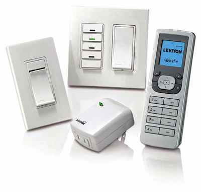
LIGHTING CONTROL SYSTEM INSTALLATION
7.09 The Installation consists of the following: –
1) Conduiting and Cabling
2) Switch Actuator panel/Lighting control panel .
3) EIB Power Supply / Line Coupler
4) Universal Interface / Switch Sensors.
7.10 Conduiting and Cabling
PVC conduiting / GI conduiting or trunking shall be done as per approved shop drawing to pull EIB & Bus Cable for all field devices and control panels.
7.11 Switch Actuator panel .
1) These shall be mounted in purpose made enclosure and adjacent to lighting distribution board in the electrical room
2) Power Cables from the lighting DB shall be terminated at the In comming terminal with proper care.
3) Out going circuits to light fittings shall be terminated at the out going terminal of the switch actuator
4) Physical address for each actuator panel shall be written in front, In bold letters.
7.12 EIB Power Supply & Line Coupler
1) Power Supply unit & Line Coupler shall be mounted in the same enclosures of actuators or in separate enclosures as per lighting control system manufactures design drawings.
2) The auxiliary voltage may not be used for other purpose than Bus.
3) Mains Supply shall be connected at Terminal L1, N.
4) Main shall be switched on once the device has been correctly installed.
7.13 Universal Interface
1) Interface shall be Installed in 3×3 back box.
2) EIB Bus cable shall be terminated at Bus terminal with correct polarity.
3) Wires which are not required should be insulated.
4) Physical address shall be written on each modules once they are programmed.
7.14 Brightness sensor
1) The lighting brightness sensor is fixed with a mounting bracket.
2) Maximum cable length should not exceed than 100 m.
3) Light sensor should not be installed in shadow.
4) If light sensor is used for external lighting it should face Eastwards/Westwards.
5) If light sensor is used for room lighting it should face Northwards/Southwards.
8. INSPECTION
Inspection I : Installation of Lighting Control System.
9. ATTACHMENTS
9.01 Risk Assessment
9.02 Inspection &Test Plan
9.03 Quality Control Procedure.