


The purpose of this method statement shall be to outline the sequence and method of Testing & Commissioning of Structured cabling system.
This procedure is one component of a complete testing and commissioning program.
This and other procedures will be used, as needed, to provide assurance that testing activities are being conducted as required by authorization basis commitments and manufacturer procedures.
SCS (Structured cabling system) is based on physical star or ring wiring topology, whichever is feasible for the network applications and capacity.
All system components of the entire cabling system will be of the same manufacturer to ensure signal warranty covering the entire installation.
Necessary Tooling & Equipment
- Fiber Termination Kit
- UTP Termination Kit
- OLTS I OTDR Fluke tester
- Labeling Machine
- Technician’s tools
- Step ladders
Precommissioning Procedure for Structured Cabling System
Installations, terminations and testing are to comply with the corresponding recommendations of the manufacturer, ANSI/ TIA/EIA, IEC & BICSI.
Check the un-shielded twisted pair category 6 will be inside the prepared containment
Check the cables are well tied with horizontal and vertical cable tray.
All data cables are in respective panel.
Labeling of all cable properly done and completed. All outlets (Data/Voice), campus/Building backbone will be labeled as per the labeling scheme approved by the consultant.
Check List for Fiber / Cat6 Cabling
A) Check & ensure that the correct Fiber/Cat6 cables are used. Physically check and verify the manufacturer’s markings. Confirm that the cables used for voice applications are Fiber cables.
B) Pre-installation cable check, check and verify the cable for cuts or damages before
C) Check for cable pair twists, physically check and verify that the cable pairs terminated in the CAT6 / RJ45 Patch Panel do not twist into each other.
D) Check for bend radius, open the compartments. Check and verify that the stipulated bend radius is not less than 4 times the cable diameter.
E) Stress Relief, Randomly check individual cables for cable stress / pulling tensions, as excessive stress on the cable may cause micro bending.
OTDR Testing Procedure
As we mentioned earlier, OTDR’s are always used on OSP cables to verify the loss of each splice. But they are also used as troubleshooting tools. Let’s look at how an OTDR works and see how it can help testing and troubleshooting.
How OTDRs Work
Unlike sources and power meters which measure the loss of the fiber optic cable plant directly, the OTDR works indirectly.
The source and meter duplicate the transmitter and receiver of the fiber optic transmission link, so the measurement correlates well with actual system loss.
The OTDR, however, uses back scattered light of the fiber to imply loss.
The OTDR works like RADAR, sending a high power laser light pulse down the fiber and looking for return signals from back scattered light in the fiber itself or reflected light from connector or splice interfaces.
At any point in time, the light the OTDR sees is the light scattered from the pulse passing through a region of the fiber.
Only a small amount of light is scattered back toward the OTDR, but with sensitive receivers and signal averaging, it is possible to make measurements over relatively long distances.
Since it is possible to calibrate the speed of the pulse as it passes down the fiber, the OTDR can measure time, calculate the pulse position in the fiber and correlate what it sees in back scattered light with an actual location in the fiber.
Thus it can create a display of the amount of back scattered light at any point in the fiber.
Since the pulse is attenuated in the fiber as it passes along the fiber and suffers loss in connectors and splices, the amount of power in the test pulse decreases as it passes along the fiber in the cable plant under test.
Thus the portion of the light being back scattered will be reduced accordingly, producing a picture of the actual loss occurring in the fiber.
Some calculations are necessary to convert this information into a display, since the process occurs twice, once going out from the OTDR and once on the return path from the scattering at the test pulse.
There is a lot of information in an OTDR display. The slope of the fiber trace shows the attenuation coefficient of the fiber and is calibrated in dB/km by the OTDR.
In order to measure fiber attenuation, you need a fairly long length of fiber with no distortions on either end from the OTDR resolution or overloading due to large reflections.
If the fiber looks nonlinear at either end, especially near a reflective event like a connector, avoid that section when measuring loss.
Connectors and splices are called “events” in OTDR jargon. Both should show a loss, but connectors and mechanical splices will also show a reflective peak so you can distinguish them from fusion splices.
Also, the height of that peak will indicate the amount of reflection at the event, unless it is so large that it saturates the OTDR receiver. Then peak will have a flat top and tail on the far end, indicating the receiver was overloaded.
The width of the peak shows the distance resolution of the OTDR, or how close it can detect events.
OTDRs can also detect problems in the cable caused during installation. If a fiber is broken, it will show up as the end of the fiber much shorter than the cable or a high loss splice at the wrong place.
If excessive stress is placed on the cable due to kinking or too tight a bend radius, it will look like a splice at the wrong location.
OTDR limitations
The limited distance resolution of the OTDR makes it very hard to use in a LAN or building environment where cables are usually only a few hundred meters long.
The OTDR has a great deal of difficulty resolving features in the short cables of a LAN and is likely to show “ghosts” from reflections at connectors, more often than not simply confusing the user.
Using The OTDR
When using an OTDR, there are a few cautions that will make testing easier and more understandable.
First always use a long launch cable, which allows the OTDR to settle down after the initial pulse and provides a reference cable for testing the first connector on the cable.
Always start with the OTDR set for the shortest pulse width for best resolution and a range at least 2 times the length of the cable you are testing. Make an initial trace and see how you need to change the parameters to get better results.
UTP CABLING
Testing UTP Cabling
Since Cat 5e/6/6A UTP cable is used to the fullest extent of its performance envelope, comprehensive
performance testing is very important. There are three basic tests that are called for as part of the EIA/TIA-568 specs for all UTP cables: wiremap, length and high speed performance.
We’ll take a look at each of them and equipment needed to test them.
What Is A “Certified” Cable?
Certification has been used by vendors of testers to mean that the cable was tested and passed by one of the Cat 5e/6/6A “certification” testers which test all the standard’s specified performance parameters.
It means that the cabling meets the minimum specifications of EIA/TIA standards and should work with any network designed to operate on a Cat 5e/6 link.
Thus, a “certification tester” or “certifier” is an instrument that tests the cabling and compares it to the TIA-568 standards, certifying that the cable meets the minimum performance specifications required by the standard.
What is “Verification”?
Alternatively, cable may be tested to determine if it will carry the network signals intended for use on the cabling systems. These testers run network bit error rate tests (BERT) over the cable as well as checking wiremaps and length.
A “cable verifier” will guarantee the cabling will support Gigabit Ethernet, for example, but does not test to the TIA cabling standards, only a problem if some other usage, such as analog video, may be used.
Wiremap
Wire mapping is a simple test that confirms that each wire is hooked up correctly, with no opens or shorts. UTP intended only for POTS (plain old telephone service) voice applications actually only needs to be tested for wiremap.
Wire mapping is very straightforward. Structured cabling standards do not consider simple voice grade cable, only cable of Category 3 or above, so most cable testing will require more than just wire mapping.
Each pair must be connected to the correct pins at the plugs and jacks, with good contacts in the terminations.
A wire-mapper is basically a continuity checker that determines if pins are correctly connected.
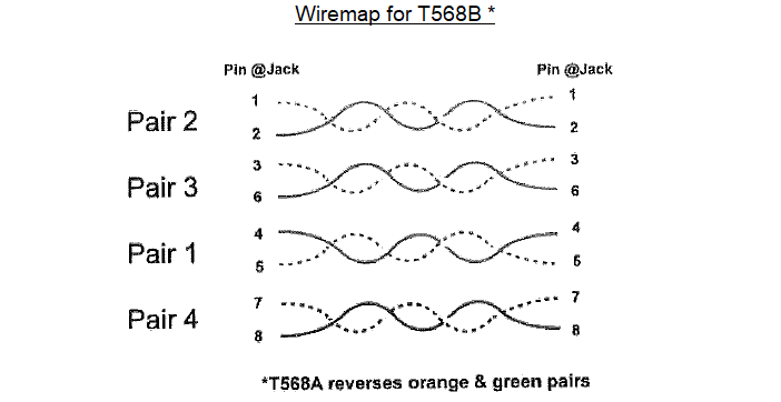

Most of the failures are simple enough to understand, like reversed wires in a pair, crossed pairs, opens or shorts. One possible failure, crossed pairs, is caused when both wires of a pair are crossed at one termination.
The usual cause of a crossed pair is a 568A termination on one end and a 568B on the other.
The most difficult wiremap problem is a split pair, when one wire on each pair is reversed on both ends. It causes the signal to be sent on one wire each of two pairs.
The usual DC wiremap will pass but crosstalk will fail. It takes a more sophisticated wiremapper or Cat 5e/6/6a tester to find a split pair, as some wiremappers which use only DC tests do not check cross talk.
In our experience, a split pair is usually caused by someone using punchdown color codes on jacks which splits the pairs.
Length of Data Cable
Since 568 cables must be less than 90 meters (296 feet) in the permanent link and 100 meters in the channel (328 feet), cable length must be tested. This is done with a “time domain reflectometer” (TDR) which is a cable “radar”.
The tester sends out a pulse, waits for a reflection from the far end and measures the time it took for the trip. Knowing the speed of the pulse in the cable (calibrated for various cable types), it calculates the length.
All cable certification or verification testers include a TDR to measure length.
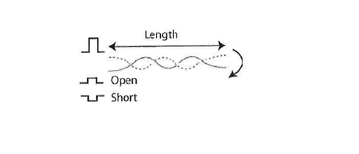

Besides measuring length, the TDR looks at the polarity of reflected pulses to find shorts or opens. If you have a short or open, the TDR will tell you what and where the problem is by looking at the return pulse, making it a great tool for troubleshooting problems.
If the return pulse is of the same polarity, the cable is open. If the pulse is of opposite polarity, the cable is shorted. If no return pulse is seen, the cable is terminated at its characteristic impedance.
Performance Testing For Certification
Performance testing for attenuation, crosstalk, etc. requires testing over the full frequency range of the cable. The frequency range for each cable type is:
Cat3: 16 MHz
Cat 5/Se: 100 MHz
Cat 6: 250 Mhz
Cat 6A: 500 MHz
Attenuation
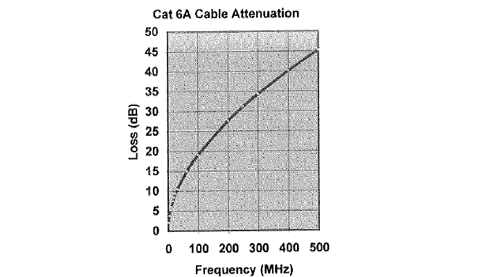
The proper operation of a LAN on the cable plant requires the signal strength be high enough at the receiver end. Thus the attenuation of the cable is very important.
Since LANs send high speed signals through the cable and the attenuation of the cable is variable with the frequency of the signal, certification testers test attenuation at many frequencies specified in the 568 specs.
This test requires a tester at each end of the cable, one to send and one to receive, then one of them will calculate the loss and record it. There are pass fail criteria for the cable at Cat 3, 4, 5, 5e, 6 and 6A max frequencies.
Here is how a typical cable attenuation changes with frequency.

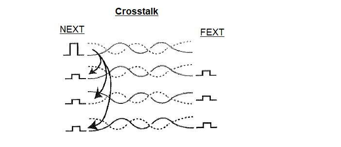
Crosstalk (NEXT)
It’s called NEXT for “near end cross talk” since it measures the crosstalk (signal coupled from one pair to another) at the end where one pair is transmitting (so the transmitted signal is largest causing the most crosstalk).
Crosstalk is minimized by the twists in the cable, with different twist rates causing each pair to be antennas sensitive to different frequencies and hopefully not picking up the signals from it’s neighboring pairs.
Remember what we’ve said repeatedly: you MUST keep the twists as close to the terminations as possible to minimize crosstalk.

Cat 5e /6 testers measure crosstalk from one pair to all three other pairs for each pair and compare it to the 568 specs, giving a pass/fail result.
Some also calculate “ACR” or attenuation/crosstalk ratio, as it is a measure of how big the crosstalk signal is to the attenuated signal at the receiver.
You want this number as big as possible, as it is an indication of the signal to noise ratio.
Tests on Cat Se/6 for Gigabit Ethernet
The additional test specs for Category 5e and 6 includes a number of new tests to insure higher performance from the cable to make it compatible with Gigabit Ethernet.
These tests relate to higher bandwidth usage of the cable and simultaneous use of all four pairs in both directions at once.
Powersum Crosstalk (NEXT) is the NEXT on one pair when all three others are carrying signals. This is realistic with 1000Base-T Gigabit Ethernet where all pairs carry signals simultaneously.
Far end crosstalk, looking at the effect of the coupling from one pair to another over the entire length, measured at the far end. As tested, it’s ELFEXT or equal level FEXT, or the ratio of FEXT to attenuation, similar to ACR.
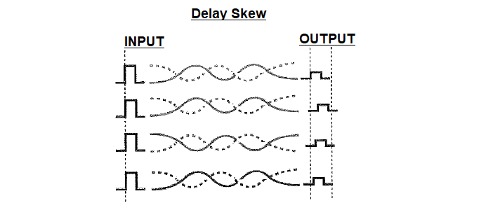
Delay Skew measures how much simultaneous pulses on all 4 pairs spread out at the far end. This measures the speed on each pair, which may be different due to the variations in number of twists (more twists means longer wires) or insulation.
Since 1000Base-T Gigabit Ethernet uses all 4 pairs with the signals split into 4 separate signals, it’s necessary to have all arrive simultaneously.
Testers measure Propagation Delay, the actual transit time on the pairs to calculate Delay Skew.

Return Loss is a measure of the reflections from the cable due to variations in the impedance.
These reflections can cause signal degradation, especially if the pairs are used in a full-duplex (bidirectional) mode. With 1000 Base-T Gigabit Ethernet transmitting in both directions on each pair, return loss can cause big problems.
The development of augmented Cat 6 (Cat 6a) cable for use on 10 Gigabit Ethernet links added a new test.
The cable is so precisely made, especially the rate of twist in the pairs, that cable pairs can interfere with the same pair in other cables nearby. This added a new test for Cat 6A which is called 11 Alien Crosstalk.”
Performing this test is time consuming and is highly dependent on the physical location of cables.
Some controversy regarding the relevance of this test exists in the industry, with some cabling vendors not requiring it.
Cable Testers
Wiremappers test the connections and Cat 5e/6 certification testers test the performance at high frequencies. Cable Certifiers test the cable according to TIA-568 standards. Cable Versifiers test the cable to see if it will transmit Ethernet signals without errors.
Cable Certification testers are mostly automated, “push a button get a pass/fail” simple. Certification testers test everything, wiremap, length, attenuation and crosstalk in one connection, give you a pass/fail result, help on troubleshooting and store the result for printing reports for the customer.
Some installers use the certification tester for all testing, after the cable is installed.
But it’s a very expensive unit that needs a trained operator and many failures are simply wire map problems. Others have each crew use an inexpensive wiremapper to make sure all connections are correct before the certification tester is brought in.
By having each crew find and fix their own wiremap problems, testing and corrections are done as the cable is installed and the cost of the certification tester is not wasted on simple problems.
It just provides the high frequency tests and documentation required by most users.
Cable Verifiers are a new class of testers that use the Ethernet communications protocols to ensure the cable supports the system intended for use on it, generally a LAN or connection to a wireless access point.
Since some UTP cables are used for non-Ethernet applications like CCTV, security or building management systems that are designed to operate on TIA-568 standardized cabling, a certification tester may be a better choice for them.
Permanent Link Adapters
The tester’s adapter interface cable may be the weakest link when testing. Conventional adapter cords may be the cause for many false failures in the field. Susceptible to the daily wear and tear associated with rough field conditions, they degrade with time and contribute to return loss, crosstalk and attenuation.
Until now, each tester used personality modules specific to each manufacturer’s Cat 6/6a cabling for testing.
The personality modules insured that the connection between the adapter and the link under test yield optimum performance and more valid tests.
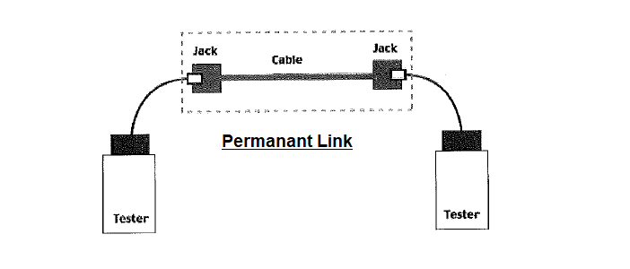
A change in the definition of the “link” was implemented in EIA/TIA568-B and ISO 11801 AM2 and it is now called the “permanent link.”
The permanent link moves the test reference point to the end of the test cable at the wall outlet or patch panel jack, including only the connector on the end of the tester interface cable.
Checklist for Testing & Commissioning of Structured Cabling
Check that approved make and recommended materials by the manufacturer/supplier are used at site.
All 22U and all other intermediate distribution frame are identified.
Check that all cable and panels are provided with proper identifications and tags.
Check and verify the cable for cuts or damages, any deformities on cable insulation before commencing the installation.
Physically check and verify that the cable pairs terminated in the CAT6 RJ45 patch panel do not twist into each other.
Randomly check individual cables for cable stress pulling tensions.
Check the bend radius.
Proper cable identification tag at both ends are placed.
Check that the entire network is clean and free of corrosion.
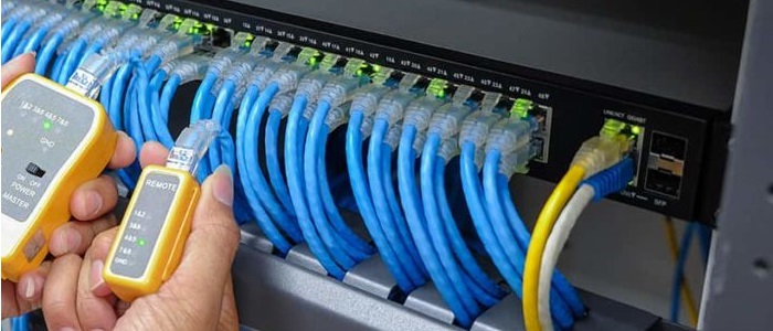
Make sure that Fluke test result is satisfactory.
Check that continuity test results are satisfactory.