


This plumbing method statement describes the procedure for the sump pump installation.
The purpose of the method statement is to ensure that work is undertaken safely, in compliance with the contract requirements and to the specified project quality requirements.
Project plumbing engineer is overall responsible for the implementation of this safe work method of statement.
As per the site conditions proper safety harness to be used and secured. Necessary personal protective equipment shall be used as appropriate according to the nature of the job. Maintain good housekeeping, excess materials, and debris shall be removed regularly.
List of equipment and tools:
- PE for all staff and labor
- Mechanical tool box
- Electric Drill Machine
- Measuring Tape & Setting out markers
- Step Ladder / Scaffolding Platform
- Chain Block/Lifting Hoist
Material Handling & Storage
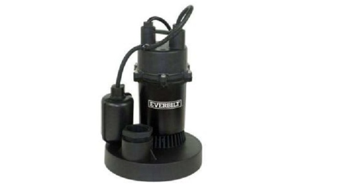
All sump pumps shall be carefully off loaded at site using the necessary manpower, appropriate shifting machinery and equipment to ensure that no damage is caused to the material. Always lift the pump by using its carrying handles / eye bolts etc.
Sequence of Work for Sump Pump Installation
Prior to start of sump pump installation it shall be ensured that the shop drawings including coordination drawings of the respective area are approved.
Ensure that the available sump pumps are as per the approved material submittal and have been inspected & approved by consultant.
Make sure that the area is released by civil contractor to proceed with MEP installations.
INSTALLATION OF SUMP PUMPS
Transfer the Sump Pumps from the stores to the working area, taking into account the make, model, capacity, and tag number, this will ensure the correct equipment is installed at the correct location.
Carefully shift the sump pump set in a safe manner using a hand trolley, fork lift, and crane as applicable to the location and lowered onto the base.
Check the pit for pumps and make sure that size of pit is as per approved drawings and enough for pump installation and maintenance.
Check the pit surface and it should be a smooth and even finish avoiding any dust accumulation. The pit surface shall be cleaned before installation of pumps.
The location of the pumps shall be marked as per approved shop drawings in the sump pit.
A 15 mm steel rod will be fixed at top end of the pit and other side to floor through L Bow hole for sump pump easy lifting.
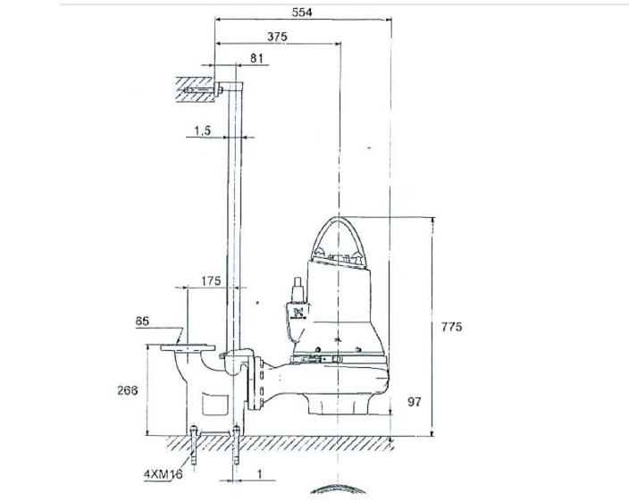
By using the drill machine prepare 4 numbers Ml6 holes in floor to fix the pump related flanged L bow as shown in below figure. Flanged L bow should be fixed such a way that after pump fixing with L Bow pump inlet shall be at height of floor approximately 97mm. Make sure that expansion bolt will be installed before water proofing.
Pump will be fixed as per below shown figure to L bow and other side of L Bow will be connected to outside waste manhole.

All guide bars, guide bar supports, fixings, lifting chains drop rods for fixing float switches pipe supports etc. within the sump shall be of stainless steel materials.
For free standing type sump pump shall be placed in the marked location without any fixing arrangement.
It shall be ensured that the pump base is uniformly resting on the sump pit base in the marked location.
Connection of Drainage Piping for Sump Pumps
The discharge pipes from sump pump discharge to the manhole shall be UPVC Class-E-3505.
Pipe connection to pumps shall be flanged & the pipe joints shall be made using solvent cement.
The routing of the drainage pipes shall be as per approved shop drawings.
Installation of the sump pump pipes shall be as per approved method statement.
A flanged connection shall be provided between the cast/ductile iron pipes and the uPVC pressure pipe work.
Automatic on /off float switch and electrical panel will be fixed as per approved drawing and manufacturer recommendation.
Sump Pump Control Panel Installation
The sump pump control panel shall be installed in location as shown in approved shop drawings.
Location of the panel shall be marked on the wall as per approved shop drawings.
Ensure that emergency lock-off isolator switch is located at a clear visible, easily accessible and close location to the pump.
Two unitstrut GI channels of size 40X40mm shall be fixed parallelly on the wall using approved anchors & fasteners
The Control panel shall be fixed on the channels & shall be secured using approved GI bolts.
Electrical cabling & wiring to the unit shall be carried out as per approved method statement and as per the recommendation of the unit manufacturer.
Ensure all areas that require touch-up painting (scratches etc.) on all pumps have been completed. Upon completion of touch-up ensure the pumps & accessories have been cleaned.
Testing the Sump Pumps
Complete installation and start-up checks according to manufacturer’s written instructions.
Check piping connections for tightness.
Perform the following start-up checks for each pump before starting:
a.) Ensure work area is clean and safe for carrying out the activities.
b.) Check the oil level in the oil chamber.
c.) Make sure that the submersible pump is submerged in the water.
d.) Make sure that the check & gate valve is properly installed as per shop drawings
e.) Start the pump.
Engage a factory-authorized service representative to train Owner ‘s maintenance personnel to adjust, operate, and maintain the sump pumps.