

Purpose
The purpose of this method statement is to define the testing and commissioning procedure of the Diesel Generators within the project.
This includes pre-commissioning checks, commissioning tests and system interface tests.
Scope
The scope of this method statement is to define the system checks, type and duration of testing that will be required to test standby generator sets to bring it into a fully working and approved mode of operation.
System Description
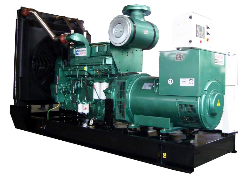
There is one generator which will provide power to the emergency and life safety systems in the event of a mains failure.
| Location | Gen Set Model | plant No. | Plant Capacity | Engine Make | Engine Type | Alternator Make | Alternator Type |
| PCS 450V | ***** | 450KVA | VOLVO | TAD1345GE | STAMFORD | ||
Interfaces
After successful commissioning of Diesel Generator as a standalone piece of equipment, it will be interfaced with the ATS panel located within the LV Main Distribution Board and tested for its Auto operation, by simulating a Mains power failure.
BMS interface to be done though RS 485 Generator panel.
Tools Equipments and Calibration
- Clamp Meter (Amp Meter)
- Laser gun (Heat detector Meter)
Load Bank :
1) 1 x 1145kVA; 400V, 50Hz 0.80pf reactive load bank.2) 6L of 20m x 240mm² / 1C LV power cable including earth and neutral cable.3) 1 x HHT100 c/w 10m lead.
References
Testing and commissioning will to be done according to the following codes & standards:
- BSS Specifications. BS 5541
- BS 7671 – Requirements for Electrical Installations.
- NFPA 30 – Flammable and Combustible Liquids Code; National Fire Protection Association; 2003.
- NFPA 70 – National Electrical Code; National Fire Protection Association; 2005.
- NFPA 101 – Code for Safety to Life from Fire in Buildings and Structures; National Fire Protection Association; 2006.
- NFPA 110 – Standard for Emergency and Standby Power Systems; National Fire Protection Association; 2005.
- CIBSE Guides.
- British Standards.
- CSA, EN, ISO, IEC and UL codes listed below:
- CSA C22.2 No14
- CSA 282
- CSA 100
- EN61000-6
- EN55011
- FCC Part 15 Subpart B
- ISO8528
- IEC61000
- UL508
- UL2200
- UL142
Definitions and Abbreviations
The following definitions and abbreviations will be used throughout this document;
Client :
Consultant :
Contractor :
Abbreviations
HCT : High Coolant Temperature
HOT : High Oil Temperature
LOP : Low Oil Pressure
AMF : Auto Mains Fail
ATS : Automatic Transfer Switch
AC : Alternating Current
DC : Direct Current
Manufacturing / Installation Handover
Installation work should be complete by MEP contractor and ready for commissioning. All installation checks must be carried out and approved by the relevant parties.
Furthermore the generator room must also be sufficiently completed to facilitate successful and accurate testing and commissioning to be achieved i.e. completion of construction work etc.

Pre – Commissioning Phase
The following pre – commissioning checks will be made to each generator:
| a) All connections are tight and leak proof, including cabling to auxiliary terminal box. | Physically checked and tighten. |
| b) All protective coverings used in packing are removed. | Physically check. |
| c) Check the fuel, lubricating oil and coolant levels are adequate; top up if necessary | Coolant and oil will be filled at site. Fuel will be supplied by contractor. |
| d) Charge battery and connect to unit | Batteries are dry charged; they will be filled with electrolyte at site. |
| e) Check alternator connections. | Physically check. |
| f) Check fuses are in holder (if exists). | Physically check. |
| g) Isolate circuit breaker from load. | Switch off circuit breaker. |
| h) Make sure the generator operating switch in the off position. | Physically check. |
All the above data will be recorded on our check sheets which are contained within section 8.3.
Safety Cones and Warning tape will be placed around Generator room and warning sign board will be kept to indicate unauthorized personals not to enter in the area.
During start up and testing Generator, sound level of about 120db will be observed so ear protection head sets will be worn by each one.
Commissioning Phase
Commissioning Procedure / Commissioning Strategy
Commissioning will be carried out as per below sections I, II, III and applicable electrical specifications. All test formats shall be in commissioning agent’s approved format.
- Commissioning Checks:
| a) Check the exhaust flow is not obstructed or damaged in order to avoid harmful fumes. | Visual Check |
| b) Check that the ventilation system is not obstructed. | Visual Check |
| c) Connect the Battery Cables to the Generating Set. | Connect battery cable to starter Motor and batteries. |
| d) Check if the Generator is IN RUNNING Status. | Test run |
| e) Run Generator for 5 minutes without load and Record the following: | |
| · Oil Temperature | : …………………………… | Degree0 C. |
| · Engine Temperature | : …………………………… | Degree0 C. |
| · Oil Pressure | : …………………………….. | Bar/Psi |
| · Engine Speed | : …………………………….. | RPM |
| · Output Voltage | :……………………………. | Vac |
| · Output Frequency | : ……………………………. | Hz. |
| · Phase Rotation | : ……………………………. | |
| · Function of all Instrument | : …………………………… |
Before commencing load test demonstrate following operations shutdown devices and Alarms.
| 1) Fail to Start (Over Crank) | Starter motor solenoid wire will be removed. |
| 2) Emergency Stop | Press emergency while engine running. |
| 3) Auto Start | Short Remote start terminals. |
| 4) Over Speed | Reduce set point below actual speed. |
| 5) High Engine Temperature | Ground sensing terminal |
| 6) High Oil Temperature | Ground sensing terminal |
| 7) Low Oil Pressure | Ground sensing terminal |
| 8) Alternator Under/Over Voltage | Increase / decrease voltage on AVR. |
| 9) Battery volt low | Increase set point above actual voltage. |
| 10) High winding temperature | Open circuit Temperature sensor wiring |
| 11) Radiator Low coolant level | Drain coolant below switch level |
All above will be recorded in our standard format attached herewith.
Performance Test ( Load Test)
Standard performance testing is a test to ensure that a generator set will give the required 100% output at specified voltage and frequency.
Interface load bank to generator
Load bank and cables will be brought to site in a truck offloaded and placed approximately 20 Mtrs away from Generator.
Temporary flexible cables will be supplied and terminated by Site technology co. and laid above the ground with warning signs around and will be terminated to the bus bar’s of load bank terminal and generator output ACB terminals with bolt & nut as follows;
Cable combination
- 1145kVA Reactive load bank = 1c x 240 mm x 2 runs per Ph. +1run neutral + 1 run for earth.
- Start the set and adjust voltage and speed to required value.
- Check that all the control equipment meets the functional requirement of the built
- Apply 50% rated load and record all parameters.
- Add 25% of rated load to achieve 75% of load and record all parameters in the format.
- Add 25% load to achieve 100% of rated load and record all parameters in the format.
- At 100% load run the set for 7 hours and checked every 30 minutes to see that the engine normal operating temperature range, oil pressure drop are not exceeded.
- Add 10% over load and run set for one (1) hour. Record all parameters every 15 minutes.
- Remove rated load and allow the set to stabilize for 5 minutes.
- Check the set for Oil leak, coolant leak and any loose items.
- Shutdown the set.
- Disconnect temporary load cables role it back, load on truck cables and load bank and Shift it to ST Store.
In addition to above, below requirements shall be complied as mentioned in the electrical specification.
With 100% rated load, operate set for seven (7) hours continuously and without interruption at 50 deg. C ambient, taking readings at thirty (30) minute intervals, and record following:
- Time of reading.
- Running time.
- Ambient temperature in Deg. C.
- Lube oil pressure in kPa.
- Lube oil temperature in Deg. C.
- Engine coolant temperature in Deg. C
- Exhaust stack temperature in Deg. C
- Alternator voltage, phase 1, 2 and 3.
- Alternator current, phase 1, 2 and 3.
- Power in kW.
- Frequency in Hz.
- Power Factor.
- Battery charger current in A.
- Battery voltage.
- Alternator starter temperature in Deg. C.
At end of seven (7) hour run increase the load to 110% of the rated value, and take readings every fifteen (15) minutes during one hour of operation.
Before commencing eight (8) hour run, demonstrate following shut down devices and alarms:
- High engine temperature.
- Low lube oil pressure.
- Short circuit.
- Alternator overvoltage.
- Low battery voltage, or no battery charge.
- Manual remote emergency stop.
- Reverse power.
- High lube oil temperature.
- Alternator low voltage.
- High winding temperature alarm.
- Radiator low water level.
Next, install continuous strip chart recorders to record frequency and voltage variations during load switching procedures, with chart speed of 1.3mm/s.
Each load change delayed until steady state conditions exist. Switching increments to include:
- No load to 80% load to no load.
- No load to 70% load to no load.
- No load to 20% load to no load.
- 20% load to 40% load to no load.
- 40% load to 60% load to no load.
- 60% load to 80% load to no load.
Demonstrate (as specified):
- Automatic starting of set and automatic transfer of load on failure of normal power.
- Automatic shutdown of engine on resumption of normal power.
- That battery charger reverts to high rate charge after cranking.
- Demonstrate low oil pressure, high engine temperature shutdowns and radiator low water level by removing sensors / switches and installing test devices to simulate low oil pressure and high temperature without subjecting engine to these excesses.
- Temperature and low oil pressure sensors shall be tested on a test stand in presence of Engineer or designated representative before commencing.
Generator control panel shall be tested as follows for each section.
- High Pot Test.
- Operating check of meters.
- Instruments and relays under service tests by impressing properly phased current and voltage.
- Operation of breaker control, sequence and interlocking circuits.
- Operation of panel in conjunction with generator set to demonstrate proper operation as a system.
NOISE AND VIBRATION
- Install, balance and adjust the generator systems equipment and associated systems to avoid noise generation at system components.
- Provide suitable attenuation to the generator air intake and acoustic enclosure to ensure a noise level of 70 dB(A) is not exceeded at 1m from the generator plant room, with all emergency power generation sets operational.
- Noise Measurement
The Contractor shall record noise levels:
- at other locations as nominated by the Acoustic Consultant or Planning Authority.
- at site boundaries when all generator sets installed under this contract are operational
- adjacent any office space of the building
- at one meter outside the air intake and discharge positions
- at one meter from generator sets when operational
- background ambient
- Perform noise measurements in the presence of the Builder to test noise levels are within specified limits.
- Carry out noise measurements to confirm background ambient as design basis. Final measurements shall be performed during site testing and commissioning.
- Noise measurements shall be made with a sound level meter and octave band filter set of approved manufacture. Calibrate the meter prior to and after noise measurements.
Vibration Mounting
Machinery shall be statically and dynamically balanced and shall be isolated from acoustic enclosure as required.
All tests specified here in before shall be repeated on site upon installation of generator set and associated equipment in the presence of the Employer and the Engineer.
Interface Test Procedures
- Prior to auto operation test, it will be checked that all power and control interconnection between Generator and ATS panel are done and ATS panel is ready to energize.
- Test procedure for automatic operation, Gen set selector switch should be in Auto position, mains fail to be simulated at ATS panel, in turn ATS will initiate start /run command (close contact) and generator will start with a delay of 2-3 seconds and will accept load within 10 seconds. Upon removal of start/ run command (open contact) generator will cool down for 3-5 minutes and will come to rest and will be ready for next command.
System Demonstration
On completion of commissioning system, operation will be demonstrated to client engineers & other related authority.
Commissioning Documentation
After completion of commissioning, all test certificates of pre- commissioning, Commissioning, Performance test/ load test, will be submitted in hard copy.
Attachments.
- Commissioning forms
- Load test forms