

The purpose of this safework method statement is to establish the work method for supply and installation of mild steel pipes, fittings and pipe works under the water reticulation work for project buildings, landscape, infrastructure and associated works.
Upon delivery at site, pipes and accessories shall be carefully unloaded and stored in a designated area and covered in plastic or polystyrene sheets.
The receiving inspection is carried out to ensure materials delivered in accordance to manufacturer’s requirements.
Inspection and verification shall be done on the delivery order. This inspection shall to be performed by the main contractors Site Supervisor, the consultant and the relevant party(s).
Rejection or acceptance of material delivered shall be by the discretion of the inspection parties.
Following tools machines and size of MS pipe & fitting to BS 534 shall be used:
100 mm dia,
150mm dia,
200mm dia,
250mnm dia
300mm dia
Survey Instruments, Excavator, Bolt / Nut, spanner, welding machine.
Installation Method of Water Reticulation System
The piping route shall be checked as per the construction drawings. Any adjustments of the installation due to the site constraint, shall be obtained from the resident engineer and approval must be granted before proceeding.
Surveyor shall carry the survey setting out and all piping routes shall be indicated on the ground by placing sand along the excavation line. Checked shall be carried out by the site superintendent before proceed with the excavation.
Upon reaching the formation level (approximately 1.0m below ground level), a plain compactor shall be used to level and compact the formation platform and all pipes and fittings shall be cleaned of soil and dust and free from crack and distortion. Laying some bricks underneath to reframe any movements of pipelines shall support pipes.
Jointing of Piping Works
Connection of pipe to pipe shall be fillet welded and pipe to fitting shall be flanged end via bolts and nuts. Where pipes to be jointed by welding it shall be carried out by the highly skilled welder.
Where pipes are to be jointed by the sockets and spigots to be welded shall be cleaned to the bright metallic finish, the spigot end shall be forced inside so that the spherical surfaces are in contact and that the gap between the pipes at the end of the spigot is not more than 1.5mm.
The weld shall be of the convex full fillet type for lap welded joints and before welded over any previous joints, wire brushing shall clean all slag.
All bare metal upon welding shall be thoroughly cleaned and immediately coated with a primer solution and be completely running over by bitumen into the metal mould placed over the joints.
Pipes and fittings installed in the locations, which may be subject to mechanical damage, must be suitably protected, including during the construction stages.
In the event of bends, tees, valves jointing shall be carried out by a Table E flanged welded to the pipe.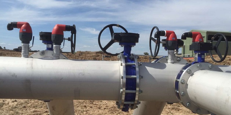

When making a flanged joint, wire brushed the pipe end to remove any protective material adhering to the coating and exposed the metal surface, welded the table E ring carefully in position remain undistorted and fastened the bolts to the pipe and fitting with a rubber ring in between to prevent leakages.
Mass concrete or thrust blocks shall be laid underside of pipe at all points of deflection in the pipeline (bends, tees, reductions, expansion, valves, etc.) and the thrust blocks must have cured for 24 hours before pressure testing is allowed. The inspection and water tightness test to be carried out and confirm by the supervising engineer.
Upon completion of testing (to the satisfaction of the client), backfilling shall be carried out strictly according to the construction drawing and specifications with proper compaction and to the satisfaction of the consulting engineer.
Water Reticulation Piping Pressure Testing
After a length of pipeline has been completed it shall be tested as a whole against stop ends. The testing shall be carried out over length of approximately two kilometer where possible between washout or over crossings or length pre-determined by engineer.
All valves shall be checked before the test to ensure that all are in working order.
The length of pipeline to be tested must seal with end cap with an extended 1 inch GI pipe that comes with stopcock together with a pressure gauge.
The test pressure to be applied shall be determined by the consultant which is generally at 1.5 times the working pressure or proposed at 15 bars.
Clean water shall be filled and pumped to the required pressure and maintained testing for 24 hours.
After a period of 3 hours or a pressure fall of 9 meter whichever is the sooner, pumping shall be resumed and the quantity required to be pumped, in order to restore the test pressure, divided by the time, shall be measure of the rate of loss.
The pipeline under testing shall be deemed to have passed if the leakage does not exceed 10% of the proposed 15 bars.
Consultant will attend all testing and will issue a certificate for pipeline passing the pressure test.
Likewise the contractor shall rectify and locate any leakages and make well all joints to the satisfaction of the client, and carry out retest until the permissible losses are complied with.
In-progress Installation Inspection
The in-process pipeline inspection shall be carried out to ensure conformance of the installation works.
A “Request for Inspection” form shall be forwarded to the consultant to request for inspection to be carried out on the particular work.
The inspection result shall meet the requirement as stated in the approved methodology.
| Check List: Pressure Testing | Mild Steel Pipe And Fitting Installation | |||
| Location: | ||||
| Location | Initial Pressure ( psi) | 24 hours later (psi) | Remarks | |
| 1. | ||||
| 2. | ||||
Quantity of water Loss:
| Duration (hour) | Initial | 3 hours | 24 hours |
| Volume of water loss (liter) |
Testing & Commissioning Inspection
The testing & commissioning inspection shall be carried out prior to handing over of the system. A “Request for Inspection” form shall be forwarded to the consultant to verify on the complete system function-ability and acceptability. The testing result shall meet the specification and code of requirement as stated in the approved methodology.
Installation Checklist
- Visual inspection for condition of pipe after placed and installed
- Inspection on alignment and levels of pipe work placed at required levels as per Construction drawing
- Physical inspection for quality for tee, coupling and bend installation.
- Installation of end cap, pressure gauge etc.
- Valves condition and function ability
- Fire Hydrant location and function ability
- Pipes and fittings condition and cleanliness
- Pipe Markers