


This electrical method statement covers the installation of bus bar electrical assemblies.
Following this procedure shall ensure that the installation has been carried out as per contract requirements and best practices.
Method gives details of how the work will be carried out and how related health and safety issues and controls shall be implemented.
A pre-construction conference or toolbox talk will take place to brief all operatives on this method statement.
All operatives will attend the Project Safety induction prior to commencing work on site.
As a minimum a Daily Briefing will explain and discuss:
- The day’s work for the gang and individuals
- planned sequence of work
- plant requirements
- materials requirements
- trades handing over / handing back
- other trades and their work in the vicinity
Necessary Tools & Equipment
- Drill machine
- Scissor Lift
- Portable electric drill,
- Slings and Hook
- Chain Pulley Block
- Forklift
- Step Ladder
- Flat form scaffolding
- 1kV Digital Insulation resistance tester
- Digital Multifunction tester
- Digital Clamp Meter
- Electrician hand tools
- Helper’s tool box
- Spirit Level,
- Water tube & Plumb
- Torque Wrench
- Set of Allen Wrenches
- Set of spanners
- Hammer
- Hacksaw
- Marker and Masking tape
Handling Lifting and Storage of Busbar Assemblies
Below are the guidelines provided to reduce risk of injury to personnel and damage to equipment during transport and Installation of busbar sections.
P.P.E. (Personal Protective Equipment) should be worn at all times in accordance with Health and Safety Regulations and specific site requirements.
When lifting busbar sections care must be taken to lift each section by its main body and not by the end sections or conductors.
If the busbar appears to have received damage during transit, remove the outer black cling film wrap and inspect the aluminium section for damage.
Any damage should be reported back to supplier/manufacture.
If not leave the protective wrap in place until the busbar is taken to its final location of installation.
While the busbar is delivered to site, a plastic end cap is provided to protect the conductors, if conditions allow this should remain fitted until the busbar is fixed to its mounting brackets and the joint is installed.
In accordance with ‘Manual Lifting Guidelines’ personnel should not manually lift goods over 25kg weight.
Weights will begiven for all busbar sections provided. If a section of busbar weighs above 25kg then means of mechanical lifting such as Geni Lifts, forklifts, etc. should be utilized.
Geni Lifts are ideal for lifting busbar sections up to the limit of the Geni Lift, they offer low level loading for operators and are easily maneuvered.
Care must be taken when using manual ‘Geni’ Lifts and a full Assessment of the Risks should be carried out by the installer before commencing works.
The busbar must be safely secured to the lifting toes of the Geni before lifting.
Vertical lifting can be carried out depending on the system being installed.
Ensure slings and hooks are rated for the load of busbar being hoisted.
Again a Risk Assessment should be carried out.
When lifting using scissor lifts or platform lifts check that the weight of the busbar sections and the installer(s) does not exceed the safe working load of the lifting apparatus.
Again the busbar sections should be secured when lifting and a Risk Assessment should be carried out.
Bus Bar Storage Requirements
The busbar will be delivered to the customer on a wooden pallet no bigger than 3200mm (length) x 800mm (width).
Busbars will be stacked neatly on the pallet for ease of removal.
The maximum weight of the pallet will not exceed 2500kg.
The busbar is protected from minor water ingress by means of an overall outer polythene wrap and individual polythene stretch wrap around the individual busbar at each end.
Stretch wrap should be left in position until the bar is mounted and joint pack fitted.
If the busbar is not to be installed immediately upon delivery it should be stored in a heated, clean, dry area not exposed to wind, rain, frost or physical damage.
Busbar should never be stored outdoors as humidity / dampness will have adverse effects on the insulation readings.
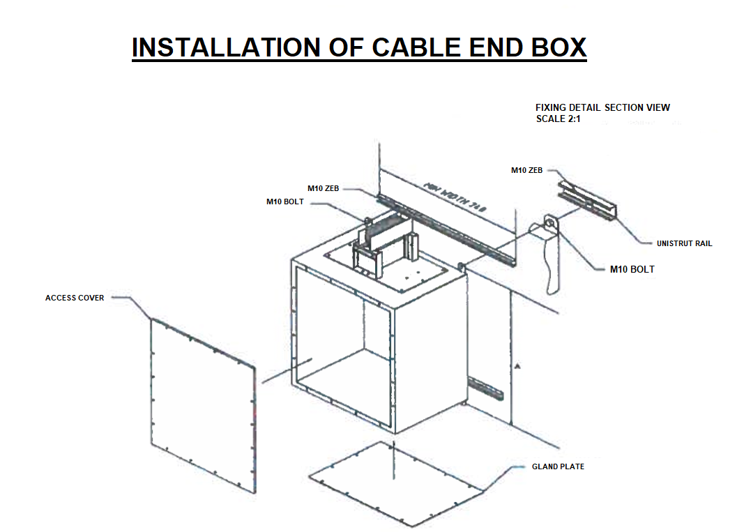
Installation of Cable End Box
This is generally the first component to be mounted on a rising busbar. Following removal from it’s packaging the product should be checked for any damage.
Supplier should be notified immediately of any problems.
The entire route should initially be inspected for any obstruction before installation. The box should be installed at the correct height in accordance with the approved drawings.
A plum line should be applied at this point from the start of the run to the end of the run to ensure vertical installation of the Busbar Run.
4no. M 10×20 bolts c/w Bellville washers and a 17mm socket is required to install the Cable End Box.
Unistrut mounting brackets are the most versatile, and allow the installer to position the Cable End Box in its final vertical plum position with ease.

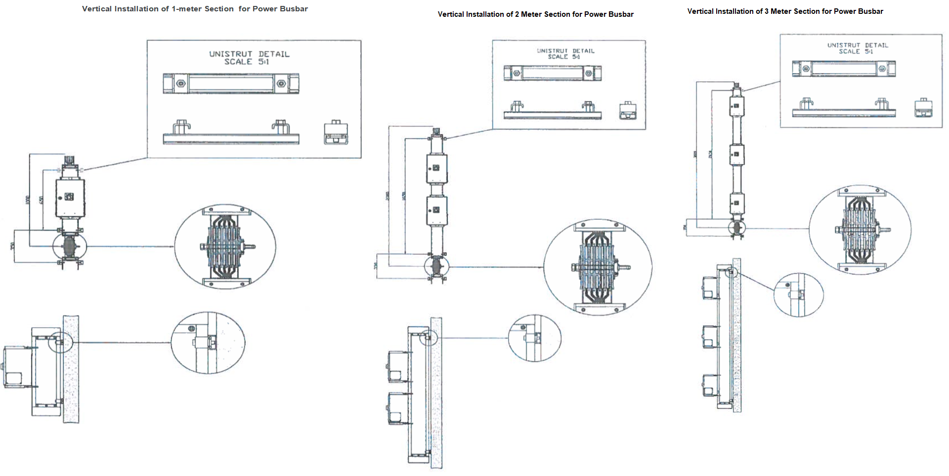
Vertical Installation OF Busbar Trunking
For vertical riser installation of sections greater than 2 meters it may be easier to lower the busbar trunking from the floor above where it is to be installed or from a fixing of the ceiling on the same floor if at the end of the run.
Care is to be taken not to damage ends of the trunking when raising from horizontal to vertical position.
Before lifting of the Busbar Section, ensure the following:
A detailed Risk assessment is to be carried out for the lifting procedure being performed in that specific area.
Fixing brackets mounted, distance between supports no greater than detail given on the installation details. Ensure that each section of Busbar has at least 2 supports.
Level and plum busbar trunking before final tightening of all joints.
Busbar standard fixing brackets must be used.
Drilling or cutting the Busbar on site is prohibited.

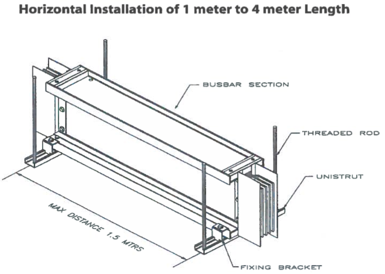

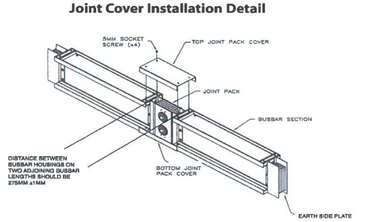

Method of Installation
Mount the busbar firmly to the unistrut as shown on details page.
Attach the rear joint pack cover to busbar.
Install joint pack, never force the joint or strike it with any object as this may damage the joint or the busbar section.
Joint should be inserted by means of constant force i.e. by pushing in by hand or by means of a suitable clamping arrangement.
Lower busbar down until the busbar touches the expansion ribs on the joint pack.
Ensure that the earth side plate is not overlapping the expansion rib.
Tighten the joint pack assembly to the correct torque level as illustrated in details.
If installed correctly the joint will appear level and no overlapping should appear.
If overlapping of the expansion ribs is apparent then the joint is not installed correctly.
Following a visual inspection for any anomalies such as foreign material etc.
Install the front Joint pack cover which is bolted directly to the rear cover.
Fix the labels supplied as per contract requirements.
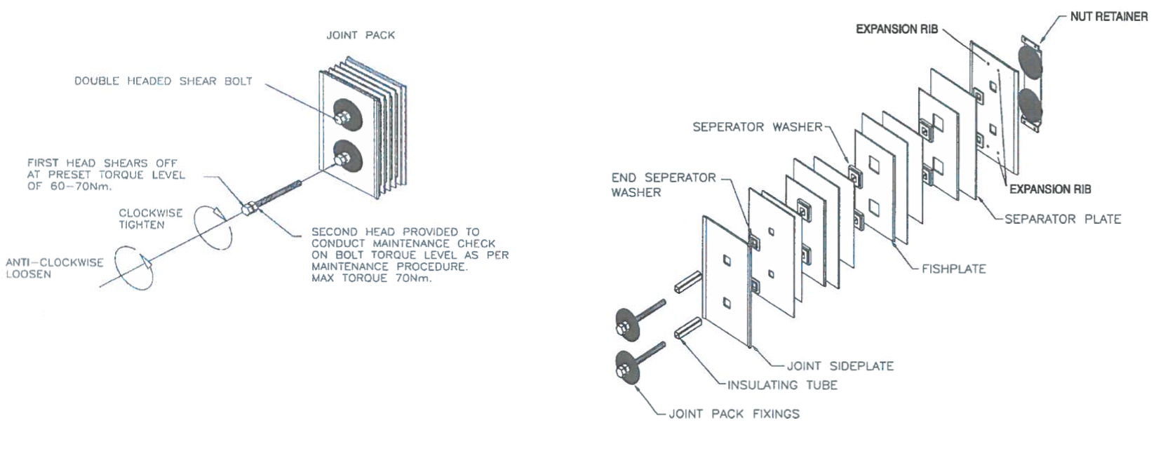
Joint Bolt Torque Details
Before joining two separate sections of Busbar trunking ensure that all contact surfaces are free from contaminates and unblemished and conductors extending from sections are not damaged or misaligned.
The joint bolt should be tightened to the correct torque level (65Nm ±5Nm) using a calibrated torque wrench with a 19mm socket.
Joint should be seated squarely and level between the two adjacent busbar sections.
Ensure the expansion ribs does not overlap the earth side plate.

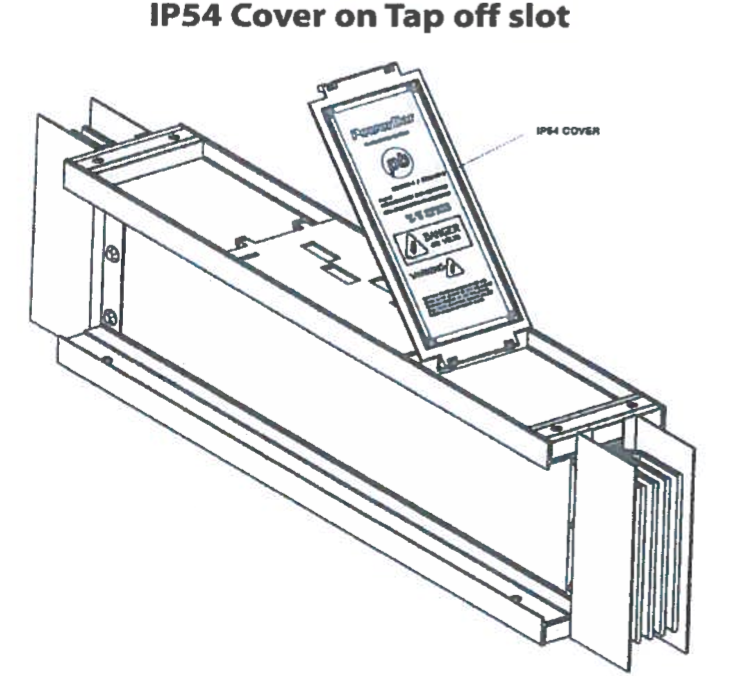
Installation / Removal of IP54 Cover on Tap off slot
Each length or distribution busbar comes complete as standard with 3 number tap off positions.
Each tap off position is IP2X in accordance with the standard, without the tap off module fitted, with the tap off installed, the rating is IP54.
A cover is required over unused tap off positions to increase the ingress protection (IP) level to IP54.
When fitting a new tap off this cover is to be removed.
The drawing below illustrates the removal of the cover.

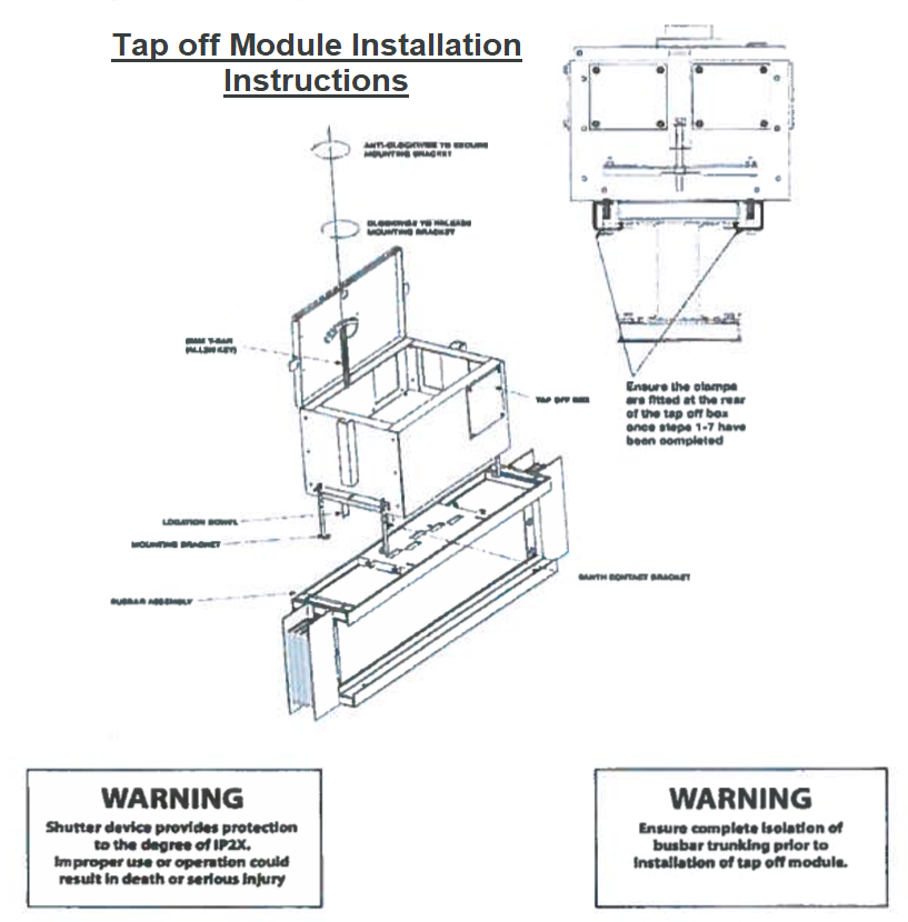
Conditions for safe Installation of tap off unit
In accordance with isolation procedures and risk assessments to be carried out by the installer, ensure complete isolation of the electrical busbar by proving dead.
Following removal of tap off unit from its packaging, check device is not damaged and tap off contacts are visually inline.
Open door using key provided and release both clamping mechanisms by rotating the 6mm t-bar in a clockwise direction.
Following completion of above step, offer the tap off box up to the shutter housing.
Visually line up the earth contact bracket and actuator to ensure correct location of the tap off contacts.
The box cannot be inserted upside down as the design of the actuator mechanism prevents this.
Following the location of the earth contact bracket and the actuator into their respective slots, insert the tap off box until base of tap off box finishes flush with busbar assembly.
Using the 6mm t-bar provided, rotate the clamping mechanism in an anti-clockwise direction to clamp the tap off box to the busbar assembly.
Install the rear fixing brackets as illustrated below.
Megger test installation prior to re-energization of bus bar.
Before turning the Breaker “ON” ensure the neutral link is connected and tightened.

Prior to Energizing
Verify that all joints have been torqued according to the recommended setting and has not been subsequently loosened.
Ensure all joint covers are firmly secured.
Ensure all tap off boxes have been correctly installed as instructed and are in the ‘ON’ position for insulation resistance testing.
Ensure all connections to the busbar / tap offs have been disconnected.
Perform a Megger Test, 2500V between each conductor and Earth.
Reading will vary widely between site to site due to length of run, humidity etc.
If readings less than 5 mega ohms are obtained measures must be taken to identify the location of the Low Resistance level and take appropriate measures to increase the resistance level.
This test should only be carried out by competent personnel. A ductor test should also be conducted to check the resistance of the joints through the entire length.
When reconnecting the system prior to Energization ensure correct Phase rotation is achieved by testing prior to energizing the supply.
Ensure all tap offs are turned off again prior to energizing.
The testing procedure should be performed and documented as per standard testing procedure available on request.
Energizing Procedure of Busbar
By following the above steps the busbar should be energized immediately.
Only authorizes, competent personnel should energize electrical circuits in line with ‘switching procedures’ and ‘permit to work’ forms provided by the site electrical supervisor.
All connected load to the Busbar Trunking via tap offs for example should be isolated prior to energizing the busbar.
The Main Supply switch to the Busbar is to be energized first.
The protection settings should be at the circuit breakers minimum protection level.
Following the successful closing off the supply breaker, close the circuit breaker(s) supplying the connected loads (via Tap-Offs) one by one.
Visually inspect the energized busbar route to look for any anomalies such as noise for example due to cover plates not properly tightened.
Maintenance of Busbar
CAUTION: LOCKOUT SWITCHES BEFORE WORKING ON EQUIPMENT
WARNING: Disconnect mains supply before removing cover
Prior to carrying out any maintenance work ensure the busbar is completely electrically isolated by isolation verification and lock off of the supply device in accordance with isolation procedures/ method statement.
Familiarization with IEE Wiring Regulations or similar Local Safety Standards should be understood in order to ensure safe isolation of the busbar Trunking.
When the busbar system has been installed / energized the building begins to take load. This load is generally of a cyclic nature, more power consumption at peak times or the day/ night, resulting in the busbar heating/ cooling constantly.
On an annual basis Thermal Imaging should be conducted on the busbar route to Identify any problems.
If Joint pack bolts come loose due to vibration from connected equipment such as transformers etc. the Thermal Imaging process should easily identify any problems.
Once identified a preventative maintenance program should be instigated with the busbar isolated as described above before carrying out any work.
If joints are found loose they should be re-torqued to the correct torque level as outlined in the installation details.
In case of loose joints where there is no sign of overheating simply re-torque the joint and conduct an Insulation Resistance test prior to re-energizing.
If slight discoloration occurs remove the joint and clean the conductor with a fine grade (240) abrasive paper. Re install the joint and megger test.
If adverse overheating has occurred contact manufacturer for further details.
Megger test results at this point could be lower than those taken during the first installation test as long as the reading does not measure below 5 Megaohms the system is satisfactory for re-energization.
Maintenance of Tap Off Module
As with the main busbar system the joints require checking on the Tap Off connections.
Thermal Imaging can Identify localized heat spots either on the:
- Connected cable
- Tap off module
- Busbar section
Upon identifying a local problem preventative maintenance should be investigated with the busbar isolated as described previously.
If discoloration has occurred on the contact due to overheating, ensure the gap between contacts are consistent and have not been damaged during transport, in case of damage contact the manufacturer/supplier.
In case joints show slight discoloration, clean them and re-tighten. If adverse overheating has occurred contact supplier for further Instruction.
Visually check the installation of the Tap off module:
- Check clamping mechanism
- Check door-Interlocking device to ensure it still operates correctly.
- Check outgoing cable connections and gland tightness/ Integrity
- Check the operation of the switching device positive ‘ON’ ‘OFF’ operation.
- Examine protective device for sign of short circuit operation.
- If a short circuit has occurred on the equipment connected to the tap off module check operation of device and the integrity of the device.