

The purpose of this method statement is to describe the detailed procedure to be followed for the installation, testing and commissioning of Elevator (Lift) at the construction project site.
This method statement is prepared also to ensure that concerned persons are familiar with the sequence of activities, utilization of resources and relevant documents in compliance with HSE and QA/QC procedures & requirements.
General Requirements for Lift/Elevator Installation
Installation method described below shall ensure an efficient, trouble free installation, while maintaining safe work procedures. The method describes a scaffold less installation sequence where the car (lift cabin) is used as mobile platform.
Ensure adequate lighting and 3- phase power supply with earthing for both the elevator and the installation hoist, temporary or permanent positioned according to the lay out drawings.
A locking off system for main power supply isolator, or other methods (For example removal of fuse, locking and tagging system, etc.) must be agreed with the building contractor before commencing installation of lifts.
Adequate single phase power supply (110 Volt) for the power tools and temporary shaft lighting for 230volt.
The shaft must be 100% ready.
Lifting hooks and ventilation duct shall be positioned in the top of the shaft according to the lay-out drawing.
Lifting hooks or dividing beam to be installed by lift supplier.
Finished floor level markings on each landing floor to be provided by main contractor.
Make sure that lift shaft and pit are cleaned and pit is waterproofed.
Transport routes on site is defined and agreed.
Suitable material storage areas agreed with the builder adjacent to the lift shaft.
Suitable storage area with locking facility for the installation tools.
Make sure that the delivery of lift installation material is complete on site.
Clear, unobstructed access routes to at least one entrance, at or next to the ground floor, for long / bulky items, route to be defined and clear of any obstructions.
All landing openings are well protected with gates and locked outside with padlock. A permit to access the shaft will be required, protection gates to be provided by elevator installer/supplier.
Safety warning signs to be placed at every landing openings/gates to warn about possible hazards.
Check that all lift shaft dimensions and tolerances are in accordance with lay-out drawings.
Suitable provision for disposal of waste materials shall be provided on site.
Welfare facilities on the elevator installation area shall be provided in compliance with applicable rules.
All call button, indicator, intercom cut-outs sleeves shall be required and provided as per GA drawings. Also lift shaft entrance height and structural opening size shall be as per GA drawing
Lift shaft handing over documents should be received from main contractor before start of work for lift installation.
Use correct and safe manual lifting techniques.
Never go under any suspended load unless it is double secured.
When working in areas with risk of falling, wear safety harness and fix it to to an approved fixing point.
Safety Requirements
The car is used as the working platform.
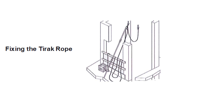
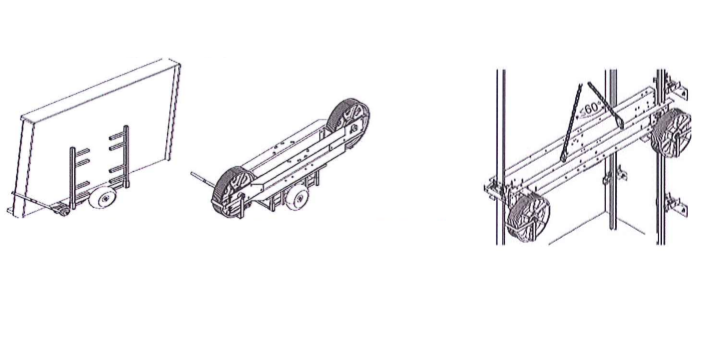
Installation hoist pulley and over speed governor are suspended from the lifting eyes at the top of the lift well.
The installation hoist (tirak) is positioned on the car roof and an additional securing rope is attached from the hoist pulley to the over speed governor hanging hook.
Elevators own/ original over speed governor and safety gear is used during installation.
ASGT device keeps the safety gear engaged/ standby whenever the car is stationary.
A securing chain (parking chain) is used to secure the car to guide rail bracket whenever the hoist hook is disconnected from the car.
All operatives are trained and use approved installation method.
Installation Procedure for Lift Hoist & Speed Governor
- Connect the three phase power supply to the hoist and check the operation of the hoist safety functions.
- Mount the hoist driven pulley on the center hook in the shaft top with the help of suspension bar and connect the hoist rope into the hoist.
- Lift the hoist into the shaft. Keep the control of the hoist on the lowest floor.
- Test the load hook capacity with the help of hoist test bracket.
- Position correctly the over speed governor hanger rod in the load hook in the shaft top.
- Slide the over speed governor on the rod, fix the governor and align the base plate.
- Slide the rope into the over speed governor groove and let the rope ends go down into the pit
Safety Checks for Hoisting the Tirak inside the Shaft
Lifting equipment and suspension points must be load marked, tested and in good condition according to the local requirements.
Hoist and lifting equipment should be 3rd party certified and should be in good condition according to the local requirements
Electrical plugs, cables and adapters must be in good condition to avoid possible electrocution
Emergency stop button and limit switches must prevent movement of hoist when contacts are open.
Safety harnesses and anchorage points must be inspected and in good condition to protect the employees from possible risk of falling.
Connect the three phase power supply to the hoist and check the operation of the hoist safety functions. Wear a safety harness and attach it to proper place.
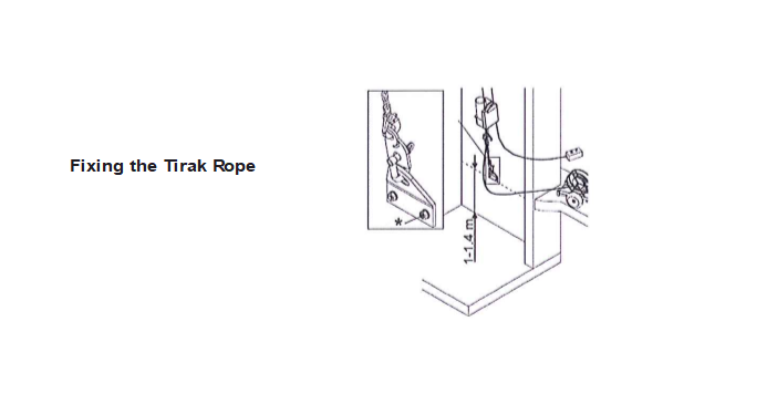
Method of Fixing the Tirak rope
Fit 4 bolts and nuts to the top part of the telescopic pipe adaptor bracket to prevent the bracket from bending during the installation.
Adjust the length of the telescopic pipe and check whether the lifting eyes can be reached safely from the landing.
Attach the safety rope of the tirak diverter pulley to the telescopic pipe using 2 cable ties and the clip the safety rope over the machine suspension eye.
Fit the tirak rope over the tirak diverting pulley and secure the axle using a safety pin.
Slide the diverting pulley coach bolts into the slot in the telescopic pipe. Lift the pulley up to the elevator shaft ceiling and clip the hook over the hoist suspension eye in the centre.
Remove the hoist test bracket and replace it after the hoist test.

Lift the hoist into the shaft. Keep the control of the hoist on the lowest floor.
Test the load hook capacity with the help of hoist test bracket. These tests will ensure that the hoist equipment will take the maximum load hoisted during the installation.
No one is allowed to be in the elevator shaft during this test.
Use the ladder to access the pit.
Install the hoist bracket in the height of 1 – 1.4 meter from the pit floor.
Attach the test plate/ mechanical fuse (breaking strength 1500 kg to 14000kg) to the hoist test bracket.
Shorten the parking chain (1500kg/ 4000Kg) to 300mm and connect the chain to the test plate/ mechanical fuse.
Run continuously upwards until the load limit of the Tirak hoist is reached or the test plate breaks – the hoist can now be used for material shifting purpose.
Position correctly the over speed governor hanger rod in the load hook in the shaft top.
Slide the over speed governor on to the rod, fix the governor and align the base plate.
Slide the rope into the over speed governor groove and let the rope ends go down into the pit.
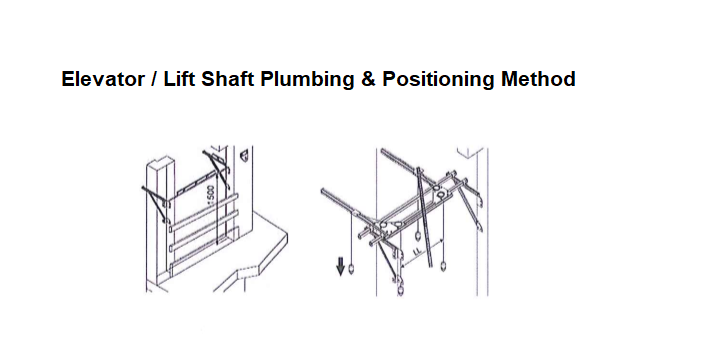
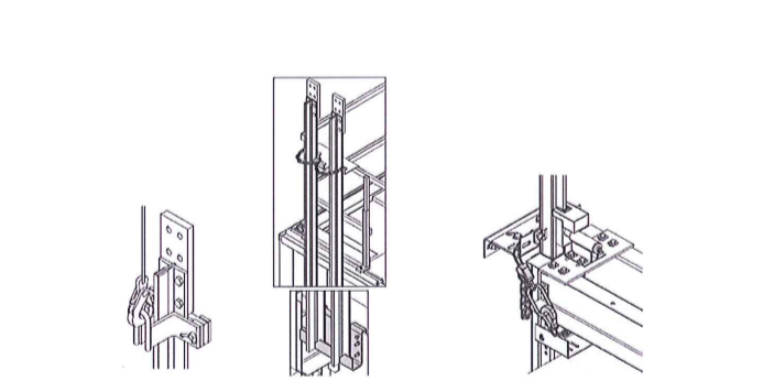
Elevator / Lift Shaft Plumbing & Positioning Method
The purpose of the plumbing is to measure the vertical straightness of the walls and openings in the lift well. Ensure that the lift equipment is in its optimal position inside the elevator shaft.
Plumbing is based on the landing door plumb lines. From the landing door plumb lines, the guide rail and motor positions are preset by the plumbing template.
If necessary, the plumbing template is moved to accommodate the worst dimension. Then, recheck at each floor level.
Arrange the shaft plumbing jig as per the shaft dimensions and distance between guide rails (DBG).
Now fix the plumbing jig support and the telescopic pipes at a minimum height of 1500mm above the top most landing floor.
Mount the plumbing jig on to the jig support and adjust the plumbing jig position in accordance with the layout drawing and tighten the jig with the help of clamps.
Hang four plumbing weights (2 for car guide rail location and 2 for front wall location) into the pit and make sure that the plumbs are steady and not moving.
Take measurements of the lift shaft and if necessary adjust the plumbing jig position.
Measure the lift well dimensions at each landing and fill the data values in the plumbing table.
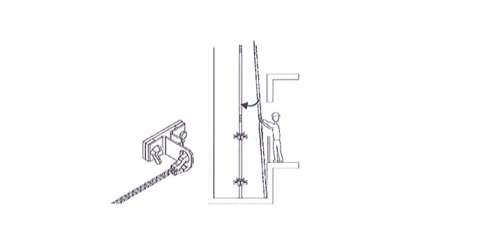
Secure the plumbing wires with the steadier brackets in the pit and check the distances between the plumbing wires are correct.
Installation at First Floor & Pit Equipment
Clean the guide rails and install the fish plates to the male ends only and hand tighten the bolts.
- The guide rail bundle may fall down when the binding straps are open. Open the middle strap first and then the outer straps. Place the guide rails at suitable working height and ensure that the cleaning surface is clear and stable during the cleaning. The rust protection must be removed from the rails for the effective engagement of safety gear.
- The guide rails and fish plates must be cleaned thoroughly using the cleaning liquid provided on the site for the purpose. Do not use any other non approved cleaning fluids, always submit the MSDS to the main contractor safety department before commencing any activity which includes use of hazardous chemical.
- Always work in a well ventilated area when working with chemicals and ensure all the precautions mentioned in the MSDS is been followed at all times.
Mount the pit ladder in its location inside the lift pit.
Check the height of the car and counter weight buffers and place it on the pit floor at the correct location and ensure its verticality.
NOTE: Before drilling in the pit area, check for any water proofing that may be affected and limitations to drilling depths.
Transfer the plumb wire position to the shaft wall using a square.
Mark and transfer the drilling hole position of car and counter weight guide brackets.
Drill all the holes for the guide brackets and fix first set of brackets rigidly.
Shift the guide rails into the pit using the hoist and support on to the shaft walls.
- No one is allowed to be inside the shaft when the rails are being hoisted inside the shaft.
- Never work under any suspended load.
- Attach the chain to the guide rail lifting clamp and let the first guide rail into the shaft.
- When entering the guide rail from any other floors than the basement and the entrance protection has been removed, the safety harness must be secured to the anchorage point fixed on the outside of the shaft.
Fix the first set of car and counter weight guide rails on to the brackets and align the guide rails for the correct DBG perfectly with the help of alignment gauges and diagonal positioning tool. Tighten all clips and bolts.
Fix the second set of brackets and align the guide rails at that location.
Construct temporary scaffolding to a height of 7mtrs measured from the bottom of the pit.
Fix the third set bracket and align the guide rails at that location.
Remove the temporary scaffolding platform.
Fix the over speed governor tension weight in the pit roping to be done temporarily.
Install the counter weight frame and insert into the counter weight guide rails and support the frame on to the buffer.
Elevator Car Installation
Shift all the lift materials, installation tools and hand tools to the appropriate locations using site trolley/ pallet.
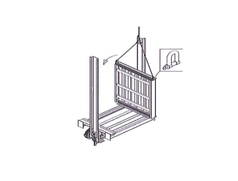
Lift the bottom beam between the guide rails – lift from the front lifting points to ensure balanced lifting
Support the pulley beam on to the buffers and guide rail lifting clamp and ensure they are on the same level – engage the safety gear lever by hand and secure the lever position using a rope to the nearest guide rail fixing to prevent accidental release.
Car Floor Installation Method
Install two lifting shackles (minimum capacity 1000Kg) to the car floor.
Lift the car floor into the car sling using the shackles.
When transporting the car floor using the site trolley ensure the load capacity of the trolley is not exceeded.
Never go and work under a suspended load
Check that the car floor is on the middle of the sling.
Protect the car floor if the final finishing has been installed.
Place the G-clamps as close as possible to the ends of the isolation profiles Re install the car sling T-bolts. Tighten them to final tightness.
Lock the floor by winding up the stop screws slightly against the fixing bolts.

Adjust the car safety gear rollers with respect to the guide rails.
Connect the over speed governor rope into the car safety gear.
Position the upper beam on to the platform and lift it by hoist and hang it on the top approximately at its correct location.
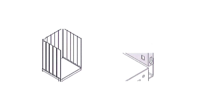
Mount the uprights and fix it with the platform and the upper beam. Check and ensure the verticality of uprights.
Fix the car enclosure panels on three sides with the platform and uprights.
If stone floors are delivered install the wall panels with extreme caution
Install the side wall to the floor slot so that the front edge is flush with the car floor front edge
Install the other side wall. Fix the wall to the floor with 2 bolts. Tighten the bolts to the final tightness.

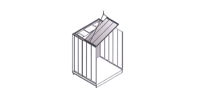
Place the ceiling panels on to the car enclosure panels and fix it rigidly.
Install the lifting eyes to the car roof C-profiles.
Place the lifting eyes so that the roof element stays horizontal when lifted up
Hoist the roof element onto the top of the wall panels. Use 2 chains – one of the chain has to be of shortenable type to avoid scratching on the car walls
Fix the kick plate and balustrade on the car roof.
Hoist Attachment Procedure in Elevator Installation Process
Do not drive the car upwards before the safety test has been performed.
Fix the hoist to the holes on the sling on the opposite side of the machine.
Install the hook anchorage and parking chain on the opposite side of the hoist.
Route the trailing flex for power cables carefully and secure it to the barricade using cable ties. Locate the power supply adapter so that it can be easily disconnected in case of emergency.
Place the rope reeler on the car roof and secure the rope to the barricade or if the rope reeler is big in size place it inside the lift cabin after securing the rope to the bottom sling
Secure the tirak with a chain to the guide rails will not fall in case the rope is slack.
Install the Automatic Safety Gear Trigger (ASGT) on the car roof and connect the rope from the safety gear arm to the ASGT.
It is essential that the rust protection is removed from the rails, otherwise the safety gear will not operate effectively
Test the operation of the automatic safety gear trigger (ASGT) and safety gear each day before commencing of work each day from the car top.
Guide Rail & Machine Installation
Fix the third ring of guide brackets by standing on the car roof.
Drive the car to the pit.
Park the car using the parking chain and the safety gear before disconnecting tirak hoist from the car.
Lift the guide rail into the lifting pocket on the car using the sliding clamp and hoist. Always control that the tirak diverter pulley can rotate on its axle and line up with the lifting point.
Secure the guide rails using the securing chain to the car roof.
Fit the brackets to the guide rails and align the guide rails.
Drive the car 1 – 1.5 meter below the next guide rail joint.
Engage the safety gear using the ASGT and attach the parking chain to secure. Remember to keep the parking chain tight.
Disconnect the hoist hook from the car.
Lift up the rail into the position using the sliding clamp from the lifting pocket.
Fix the guide rail to the fish plate
Connect the tirak hook back to the car and drive the care slightly upwards to disengage the safety gear.
Never align the guide rails with the safety gear engaged.
Move the car up and park at a comfortable working heights to install the next rung of brackets.
Attach the hoist on to the car roof as specified
Test the operation of the safety gear by engaging the ASGT and drive the car upwards and downwards.
Lift the balance guide rails upwards, fix all the brackets and align the guide rails completely by moving the car upwards by the hoist.
Remove the plumbing jig and plumb wires.
Drive the car down wards and lift the machine to the top most floor through the lift car.
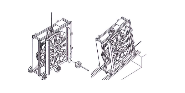
Transporting the MX machine to the op most landing.
Install wheels and axles to the machinery package, if possible use crane of the builder or forklift for lifting the machinery package.
Secure the wheels with locking pin.
If rough surfaces, use the 4 U-beams included with the machinery package.
Transport the machinery near to the lift well. Avoid moving the machinery over uneven or bumpy surfaces.
If there is a possibility of uncontrolled movement (E.g. When moving the machinery up slop) use the manual chain hoist to secure the load.
Drive the car to the lowest landing level, and bridge the gap between the car and landing using the U-profiles supplied with the machinery package.
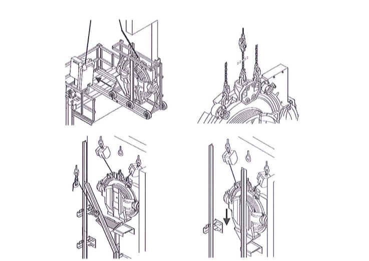
Drive the car to the topmost landing level and bridge the gap between the car and landing as before using U-profiles and push the machinery out into the landing
Fix the machinery unit on to the top most guide rail with isolations and align.
Connect one chain block to the lifting eye for the electrification panels in the top of the lift well; connect the other manual chain hoist to the lifting eye for the rope anchorage beam.
Do not attempt to install the machinery without both chain hoist and Tirak.
Remove the machine guide rail using the manual chain block
Park the car at the top most floor so that the car top beam is in level with the topmost landing level.
Engage the safety gear and secure the car with parking chain, keep the chain as tight as possible.
Pull the machinery on the sling top beam using U-Profiles and Tirak
Lift the machinery slightly to remove the U-profiles.
Locate the middle wheels in between the sling top beams and lower the machinery on top of the beam and transport the machinery in position for installation
Engage the safety gear and secure the car with the parking chain.
Connect the tirak to the top most lifting eye on the machinery using the chain rated for 1000Kg and connect the manual chain block to the casting lifting eyes on the outside.
Push the machinery package onto the car roof securing the package with the lifting equipment. Tighten the chain block and tirak when moving the package.
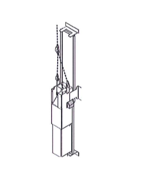
Operate from the landing
Disassemble and remove the machinery package
Lift the machinery near to the lift well wall using the tirak and manual chain hoist.
Remove the chain from the tirak and fix the tirak back to the car and drive the car to just below the fish plate of the top guide rail.
Engage the safety gear and secure with parking chain again use the tirak hoist to re install the top most guide rail which was removed earlier.
Lower the machinery on to the bed plate, and drive the car up to a suitable level to secure the machinery top fixing.

Landing Doors & Car Door Installation Method
Mark the finished floor level line at all landings.
Mark out on the car sill, the door center line and the width of clear opening.
Mark the hole / bracket positions of sill and header fixings and fix the same using expander bolts.
Fix the sill and header and check the alignment of the same.
Lift the door panels through the car and install and align the door panels.
Repeat the same procedure for all floors except the top most landing.
In place of one side frame, install the control cabinet at top most landing and align vertically.
Align the door panels at top most landing.
Install the front entrance panels of the car.
Mount the brackets for fixing the car door operator fix and align the door operator.
Fix sill and header for the car door and align the car door panels.
Ensure the protection against damages and entry of water/foreign particle into the lift shaft.
Shaft Electrification Procedure
Transport the braking resistor, maintenance access panel, drive panel and shaft electrification panel to the topmost landing.
Fix the control panel inside the control cabinet.
Fix the shaft trunkings and lay shaft electrification bundles inside the trunking sections.
Do the wiring connection for all landing door gate locks.
Fix and connect the wiring for tension weight switch, pit stop switch and three pin socket.
Lay the travelling cable and terminate one end inside the control panel and the second end to the car top connection box.
Do the wiring from the control panel to the main switch and to the machinery unit.
Mount all landing call buttons and landing indicators and do the wiring.
Fix the Emergency Battery Drive (EBO) panel and do the wiring.
Complete all the connections in the control panel.
Fix the brake lever cable to the brake handle inside the control panel.
Fix the intercom and do the wiring.

Fixing the Travelling Cable
Move the car at least 100mm below the lowest landing level
Check that the travelling cables are correct and that the cables are not twisted.
Move the car 1 meter above the landing sill level and secure the car by engaging safety gear and securing with parking chain.
Fix the travelling cable to the travelling cable hanger and tie the rest of the travelling cable under the platform using cable ties.
Installation of Car Interiors & Car Electrification Method
Ensure that the main switch for car lighting supply is locked in OFF position.
Only us the adhesive approved by supplier of the finalizing materials. Follow manufacturer’s instruction and ensure the cars are well ventilated.
Fix the car operating panel inside the car and complete all the wirings.
Mount the brackets for the hand rail and fix the same rigidly.
Fix the curtain of lights on to the car door panels.
Fix the ceiling panels under the car roof and set the lighting inside and complete the wiring.
Fix the final limit switch, deceleration switches, synchronization switch, door zone switches on the car roof.
Fix the car top connection box.
Connect the earth wires to the earth bar.
Connect all the control switches, final limit switch, door operator cables, car operating panel cables, curtain of light cables and safety gear contact cables.
The MX machine break must be opened using the break release lever in the MAP during travel.
Roping Procedure
When roping has been completed and the car is supported on the tirak hoist, it must be ensured that the car side is heavier than the counter side. The MX machine break must be opened using the break release lever in the MAP during travel.
Lift the bottom pulley beam and place it on to the stool and set the pulley beam.
Lower the car to the pit and keep the car close to the bottom pulley beam.
Fix the pulley beam to the platform rigidly.
Fix the diverting pulley on the counter weight frame and align.
Lift the counter weight frame and place it on the correct location.
Attach the car and counter weight rope anchorage brackets to the guide rails.
Put the wire rope drum on to the car roof and complete the roping.
Connect and align all diverter pulley rope guards.
Fix the over speed governor on to the original brackets.
Fix the parking plate and align.
Install all toe guards.
Fix the car fan and do the connection.
Elevator / Lift Testing & Commissioning Method
The following precautionary steps must be taken in the specified order unless there are essential reasons for doing otherwise:
- Disconnect the power supply completely.
- Secure it against re-connection.
- Verify that the installation is de-energized.
- Check requirements for earthing in special circumstances. (This operation may only be carried out by qualified personnel in co-operation with the person responsible for the building electrification who must ensure that the technique can be safely employed in this situation.)
- Provide protection against adjacent live parts.
Prerequisites for initial Lifts Commissioning:
- Ensure the working place is cleared from unnecessary object and lockable.
- Ensure the alignment of the machinery and connection of all machinery wires.
- Ensure the fixing of the SEP panel, Drive panel and connection of wires from machinery.
- Ensure the connection power supply and earthing in the main switch and in the Maintenance access panel.
- Check the connection and tightening of all the wires in the terminals.
- Check the insulation resistance value for the motor wires and brake wires. Note down the values in the Test Report.
- Check the ohmic value of thermistors and any short circuit between controller wires to earth.
- Ensure the brake is adjusted.
- Ensure the Fuse ratings are correct in the mains isolator and in the control panel.
- Remove all the Transportation protective covers if any.
- Tripping speed reducing weights are removed from the Overspeed Governor.
- The positioning magnets are installed accurately as per the Shaft wiring Diagram.
- Check that Load weighing cable is connected as per wiring diagram.
- Car and counterweight is balanced.
Initial Commissioning of Lifts:
- Ensure the earth of the main supply is connected to the main earth of the Building.
- The earth continuity is ensured between:
- The maintenance access panel and Shaft Electrification panel.
- The maintenance access panel and car top cross connection box.
- The maintenance access panel and topmost landing Door.
- Turn the Elevator to RDF Mode (Switch 270 on maintenance access panel)
- Turn the Inspection Drive mode on the car Roof to Normal.
- Turn the POWER ON from the main switch (220) in the Maintenance access panel.
- Check the Fuse LED’s turn on (LCEREC Board)
- Set the parameters as per the motor type, load, speed, Roping by referring the Parameter table of V3F16L Drive. (784393) using the interface from MAP panel.
- Save the parameters to permanent memory.
- Switch the Power Off and ON to reset the control system.
- Check the safety circuit by pushing run button in RDF unit (270:RB) and check the Safety input LED is lit in the user interface board on the MAP panel.
- Check the safety chain operation with RDF unit and activate each switch and see that safety input LED does not light.
- Adjust the Load weighing device temporarily by adjusting the Offset potentiometer in the user interface so that the load indication shows 50%.
- Ensure no one is there in car roof when you drive the Lift for the first time.
- Check the tacho polarity and motor Direction with RDF unit by pushing Run and down button.
- Check the operation of the speed and direction LED’s are correct and the Lift cabin is running down only.
- Check the same operation from car roof from the car inspection drive unit buttons.
- Check the safeties, landing and car door contacts are operating by activating one by one from car roof.
- See that no sounds are heard while running the lift from car roof and all running clearance is O.K.
- Turn the POWER OFF after the successful operation.

Prerequisites for commissioning for normal drive and Fine tuning
- Ensure the initial commissioning is successfully done.
- Ensure the operation of the safety gear.
- Ensure buffers are positioned correctly.
- Ensure the installation of car with final decoration, and 50%balanced with the counterweight.
- Remove all unnecessary objects from the pit.
- Ensure all the Doors are aligned and adjusted.
- Ensure the pit is clean and dry.
- Ensure the cleaning of guide rails.
- Ensure the alignment of all shaft switches and Magnets.
- Ensure the counterweight screen is installed.
- Ensure pit ladder is fixed.
Normal speed test and fine tuning:
- Adjust the load weighing device.
- Drive the car just below the bottom floor with LED 61:U, 30, 77:N, and (77:S) must be lit on the board.
- Turn the Emergency drive unit to Normal mode (Car Roof Inspection Drive unit and RDF Unit in MAP Panel to OFF)
- Start the set up drive using user interface menu.
- After successful setup user interface displays – — –, lines for few seconds and Floor number on Display.
- Drive the car in nominal speed and verify the operation is smooth and stops for the desired floor.
- Check the levelling accuracy and if necessary adjust the switches / Magnets
- Do the set up again if the switches / magnets are adjusted.
- Run the elevator in normal mode for 30 minutes with various load conditions and see for any variations.
- Check for levelling accuracy and note down the readings.
- Check the car and landing indications and the call registration.
- Check the Door operations are smooth and adjust if necessary.
- Check the Door safeties are working and functioning of Door open button.
- Check the car lighting and operation of cabin fan.
- Check the overload function and the buzzer and light indication comes ON.
- Check for the Group Operation.
- Take the current readings and note down the readings.
- Do the safety test as per test report.
- Check for Fire operation.
- Check for the Emergency Battery Drive operation (EBD) during power failure.
- Check the operation of EBD (M) for balanced Load operation during Power failure.
- Prepare the test report as per the format enclosed
Interfacing of the Lifts
Fire Alarm: All the building fire cables are connected with lift controller and in the event of Fire elevator will come automatically in the main landing and opening the door for passengers Evacuation. If the Elevator in fire mode , will work only with key and this operation can done by a trained fire fighter.
Building Management system: (BMS) is a computer-based control system installed in buildings that controls and monitors the building’s mechanical and electrical equipment such as ventilation, lighting, power systems, fire systems, and security systems.
Now a day’s lift operation also monitored in the control room. In our controller we can connect, three different status monitored in the control room.
- Lift main power failure status
- Healthy status – Normal
- Alarm status.
Seismic sensors
Normally the seismic sensor switch are installed in the Elevator pit side.
This is an earth quake safety equipment, this protect the passengers while traveling under earth quake.
Seismic Switch units can disable or deactivate any elevators which may become life endangering or self destructive during an earthquake.
Elevator units are designed to reliably respond to only earthquake motions and to reject interference or false triggering from man made and non-earthquake motions.
Elevator cars are moved to nearest floors when an earthquake is detected by seismic sensors.