


This mechanical HVAC method statement covers the Air Leakage Testing of Metal Ductwork.
Procedure defines the method used to ensure that the hvac ductwork has been manufactured and installed with all required seals to suit the specified pressure classifications.
The method also gives details of how the work will be carried out and what health and safety issues and controls are involved.
Perform leak testing for horizontal and vertical installations based on Duct Pressure Classification as per the following criteria:
Low Pressure Ductwork i.e. below 500 pa Pressure no pressure testing required but some times client may require 10% of ductwork to be tested.
Medium Pressure Ductwork i.e. 750 pa to 1000 pa Pressure 25% of ductwork to be tested.
High Pressure Ductwork i.e. 1000 pa Pressure and above 100% of ductwork to be tested.
The 25% pressure test will be on the discretion of the engineer based on a visual inspection of 100% of the works.
All ductwork failing tests shall be re-sealed and retested until it meets the required criteria at no cost and time implication to the client.
References and Codes
Contract Specifications
Approved shop drawings.
SMACNA
DW 142, DW143 & DW144
Inspection and Test Plan
Project Safety Plan
Project Quality Plan
Applicable QMS Procedures
JSEA Job Safety Analysis
Related International standard ( ASME, ASTM-A653A, 653M and ASHRAE standard)
Necessary Tools & Equipment
- Leak Tasting Machine & accessories to connect the apparatus to the system (tubing, flexible hose)
- Airflow Measuring Device (Orifice Tube)
- Flow Producing Unit (Fan)
- Pressure Indicating Devices (Manometer)
- Flow Adjustment (Typically A Blast Gate)
- Sheet Metal Shear (straight, left and right) Shearing Tools
- Electric Drill
- Screw Driver
- Punching Tools
- Mallet
- Grinder
- Adjustable Wrench
- Sealant gun
- Monkey Wrench
- Vice Grip
- Vice clamp
- Steel square
- Plumb Bob
- Spanner set
- Duct stretcher
- Spirit level
- Philip screw
- Accordion type riveter
- Optional Items as per consultant requirements
Sequence of Work for Duct Leakage Testing
Disassemble, reassemble, and seal segments of systems to accommodate leakage testing and for compliance with test requirements.
Conduct tests at static pressures equal to maximum design pressure of system or section being tested.
If pressure classes are not indicated, test entire system at maximum system design pressure.
Do not pressurize ducting systems above maximum design operating pressure.
Below table shows the Maximum Allowable Leakage:
|
DUCT CLASS |
½”, 1″, 2″ wg (500 Pa) | 3″ wg (750 Pa) | 4″, 6″, 10″ wg (1000 Pa) |
| SEAL CLASS | C | B |
A |
|
SEAL APPLICABLE |
Transverse joints | All Transverse joints and longitudinal seams only. | Transverse joints and longitudinal seams, and duct wall penetrations. |
|
STATIC PRESSURE DIFFERENTIAL / Pa |
MAXIMUM LEAKAGE OF DUCTWORK Liters per second per square meter of surface area |
||
|
200 |
0.84 | ||
|
400 |
1.32 |
0.44 |
|
|
800 |
0.69 |
||
|
1200 |
0.30 |
||
| 1500 |
0.35 |
||
Remake leaking joints and retest until leakage is equal to or less than maximum allowable values.
Further duct testing is part of the testing and commissioning stage.


Leak Testing Method
Select a section of duct to be tested.
Select a test pressure (never in excess of the construction pressure class). Ideally the operation pressure.
Calculate the allowable leakage using leakage factors for the duct surface area.
Select Leak Tasting Machine (blower and orifice) suitable for the test air flow requirements (may need to divide the test section into subsections).
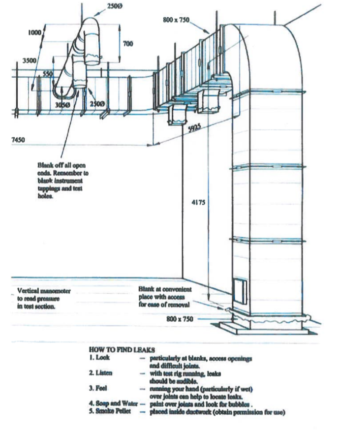
Provide temporary seals at all openings by providing fabricated GI end cap for each opening within the duct section under air leakage test, and seal it firmly to avoid any air leakage from these temporary connections.
If the duct opening has a flange than fix the end cap with matching flange with bolts and Drive cleat, Clip or Clamp and seal it by Gasket and approved sealant material.
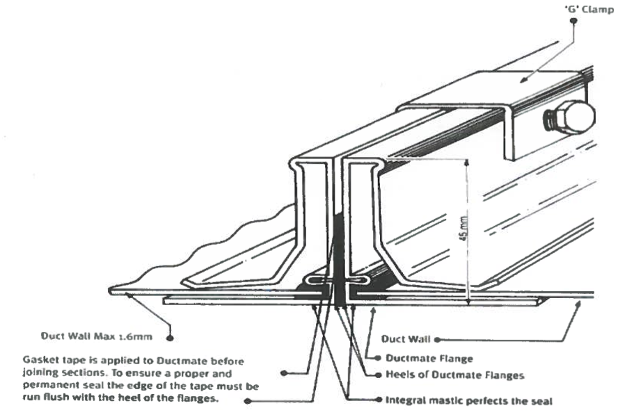

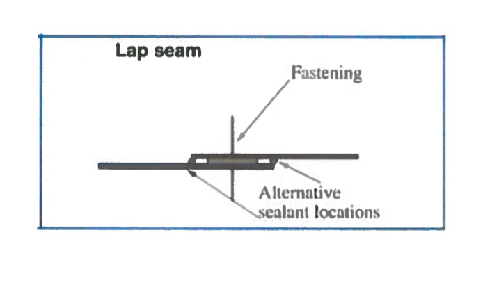
Otherwise it we be connected by lapping the GI end cap to the duct opening edge using a Gasket between and fastening by screws or rivets than to be sealed by approved sealant material as shown below:

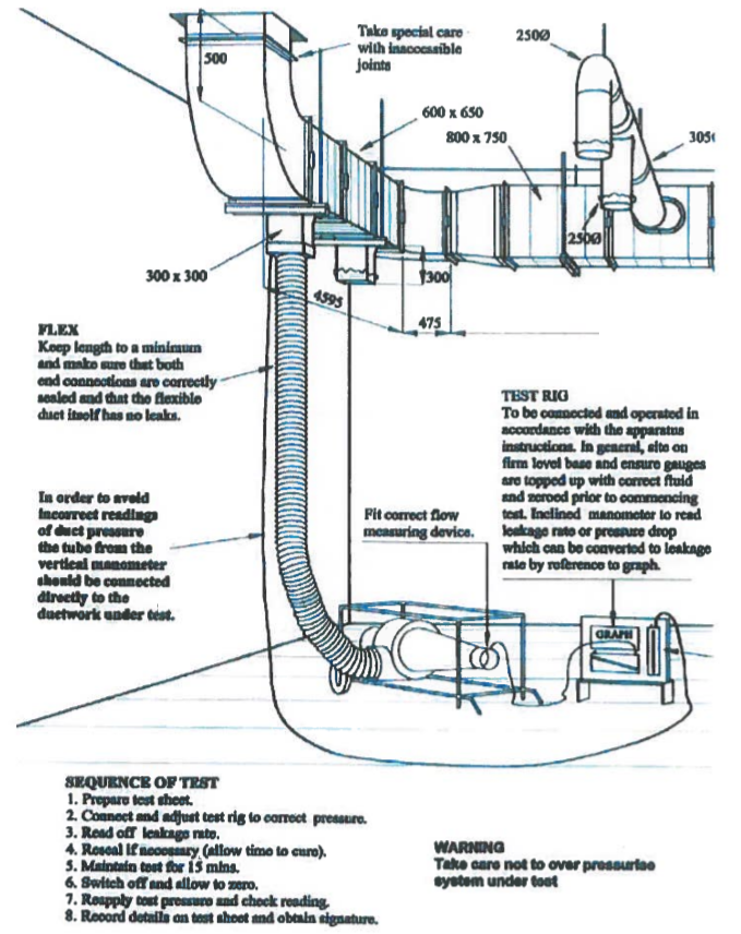
Connect Leak Tasting Machine to the duct section as per manufacture recommendation.
Start blower at low air velocity capacity & increase till test pressure is reached.
Adjust the instrument until the designed pressure is obtained (the pressure at which to test the ductwork will be determined by the designer and the installation contractor. The maximum permitted leakage rates are given in DW-143.
Check the measured leakage is within the permitted range or not.
If the leakage is not in the limit, check the ductwork and mark all points on the Duct where the air is coming out.
Sealant will be applied to the leakage joints and perform another test to maintain the leakage within the permitted limit.
Maintain the test for 15 minutes and check that the leakage rate has not increased.
Record all the details on the test sheet and compare with the allowable leakage.
Once a satisfactory duct leak test has been completed arrangements will be made following the request for inspection procedure of the project.