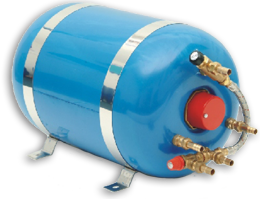
The purpose of this method statement is to define the procedure for the on site commissioning of the Calorifiers. This method statement should be read in conjunction with the relevant method statement for installation outlining the responsibility and quality verification to be performed by various parties.
Method Statement for Commissioning of Calorifiers
The manufacturer’s commissioning Engineer shall perform the calorifiers commissioning as per the following.
1. All precautions are taken against electric shock by switching off between tests and ensuring loose wires are not in contact with any metal work or in dangerous positions.
2. Immersion heater elements are tested in accordance with BS 7351. The elements are sealed during the manufacturing process however exposure to moisture can occur during transportation. Elements will operate with low insulation reading however where the resistance is below 0.5 MOhms the elements should be dried prior to operation. This can be achieved by placing a low potential difference across the elements. (Max 25% of the rated voltage)
3. Before putting the control panel into service check that all the control circuit and main circuit connections are tight using the appropriate size spanner or screwdriver.
4. After connecting the mains check & ensure that that the isolator protective cover is refitted in the correct position.
5. Remove all cable ends and other extraneous matter from the bottom of the casing. Ensure that the fuses are well seated.
6. Test the control system with the main alive and the main isolator in the ‘ON’ position but with the immersion heater mcb’s off. Testing should be as follows.
- Switch on the main isolator and with the thermostats connected the contactor should close and the plant working light comes on.
- Remove on wire from the control thermostat and the contactor should open switching off the indicator light.
- Replace wire to the control thermostat and repeat with the safety thermostat.
- During the period that the control thermostat is disconnected, and the contactor open, operate the test button and the contactor should close and the plant working light come on.
7. Before conducting the following tests ensure the calorifier under testing is full of water.
- Check all connections for tightness.
- Refit the immersion heater cover, take care not to trap any connecting cables.
- With the thermostat disabled test the contactor operation. On satisfactory completion of this operation reconnect the thermostat.
- Ensure that the control point temperature is set correctly, this is generally between 60 and 65 deg C. (The high limit thermostat should be approximately 5 deg C above the required control point temperature)
8. Ensure that the thermostats are set at the correct temperature point and as far in the pocket as possible.
9. The level switches are checked for correct operation.
10. The operating current, insulation resistance and the temperature are measured and readings noted down. These are compared with the design values. The actual values should match the design values or should be within acceptable tolerances.
11. The control panel of the calorifier is connected to the BMS system through a volt free contact and the following parameters are monitored.
- Run status
- Trip status
Quality Control
QA/QC department will monitor all the activities to ensure that commissioning of the calorifier is carried out as per specification requirements and manufacturer’s recommendations.
Safety
All the commissioning activities will be undertaken in accordance with the safety regulations laid down in the contract and project safety plan.

