Welding symbols, like sign posts are informational directors. They are placed on welding drawings by welding engineers and their purpose is to relay information to the welder. In many instances the information relayed is very simple.
Welding symbols are used on blueprints and drawings to show where the weld is to be placed and may also show the size, type of weld, number of welds, details about the weld and even details about the joint.
Welders that fabricate or work with drawing must be able to interpret the welding symbol to prepare the joint and apply a weld that has the required strength and soundness.
Occasionally it is necessary for the engineer to relay complicated information. Therefore it is important that welders understand the symbiology and are capable of interpreting the needs and directions of the welding engineer.
For the most part of the world welding symbols are standard throughout, although there are symbols that are devised and used only by the company that devised them.
Reference Line & Arrow
The reference line is one of the most important elements on the welding symbol. All the other elements that describe the weld are on or located around this line.
The reference line has a leader and arrow that points to where the information applies.
It may also have a tail that has information about the process, specification, or other notes that do not normally have an element that describes them.
If the elements on the reference line describe the necessary details (as it does in most cases) the tail is not used.
One of the most important things about the reference line and the welding symbol is the top and bottom of the horizontal line.
The actual symbol that shows the type of weld and the elements surrounding it that detail the weld can be placed on the top of the line or on the bottom of the line.
Key Points to Note:
Symbols on the bottom of the reference line mean weld the side of the joint the arrow is touching or pointing to.
Symbols on the top of the reference line mean apply the weld to the other side of the joint, or the side opposite to where the arrow is pointing.
This method is used because sometimes the welding symbol must be drawn on the blueprint on the other side of the joint.
When symbols appear on both sides of the reference line it means weld both sides of the joint.
If the reference line has a weld symbol on both sides of the reference line they may, or may not be the same weld on both sides of the joint.
Remember the rule to apply the right weld to the right side.
There are two other elements that may be seen on the reference line that provide information about the weld.
One is a circle around the place where the leader line connects to the reference line and indicates the weld is “ALL AROUND”. This means the weld extends all the way around the joint the arrow is pointing at.
Key Points to Note:
The all around element is only used when it is possible to weld all the way around a single surface. Otherwise more than on symbol is used.
The other element seen on the reference line resembles a flag and is located where the leader line joins the reference line.
This element is called a field weld and means the weld will be done in another location. For instance, this weld may be applied at the job site not in the shop. Sometimes clarification will be given in the welding symbol tail or as a specification on the print.
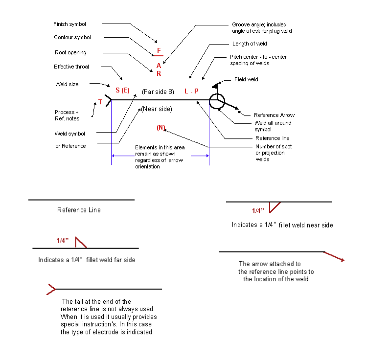
Elements of Welding Symbol System
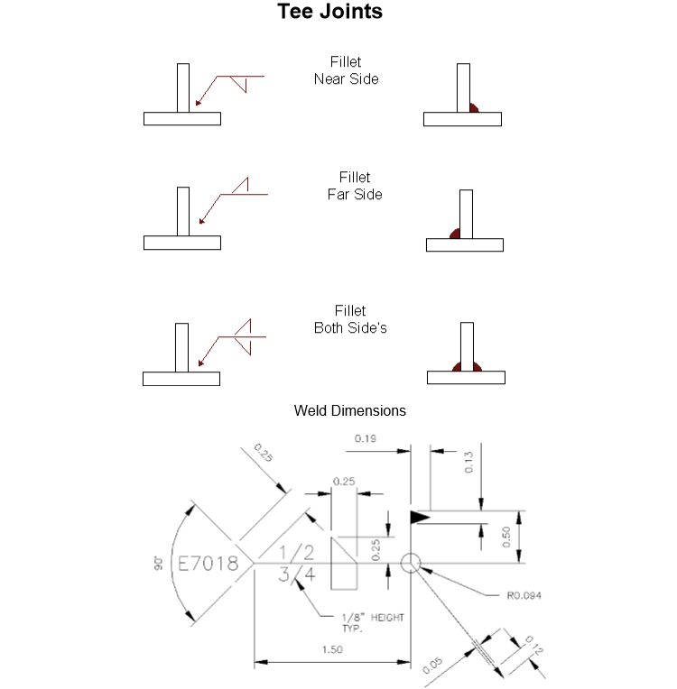
Figure below shows the various elements of a welding symbols. Let’s take a look at each element in the coming section.

When we put the above elements together we see the result in below figure. The finished symbol instructs the welding operator or welder to deposit a 1/4” fillet weld both sides of the joint and that the preferred welding rod will be a E7018.
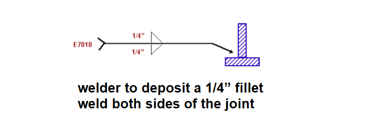

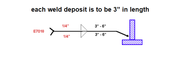
Figure below looks very similar but in this case the symbol informs the weld operator that this is a stitch weld. The first dimension indicates that each weld deposit is to be 3” in length.
The second dimension refers to the center to center spacing requirement of each stitch.
So in this case the weld operator is required to deposit a series of 3” welds with a 3” space between each deposit.
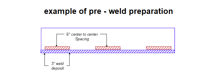
Supplementary symbols are often added to the weld symbol. A supplementary symbol usually refers to pre – weld preparation or post weld finishing. Figure below is an example of pre – weld preparation.
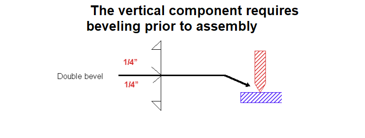
The symbol shown in figure below indicates that the vertical component requires beveling prior to assembly.
The remainder of the symbol indicates that a 1/4” fillet is required to complete the weld.
This welding symbol would usually be accompanied with additional notes and instruction.
The additional notes would probably reference a specific weld procedure, which would indicate the number and sequence of multiple passes required to complete the finished weld.
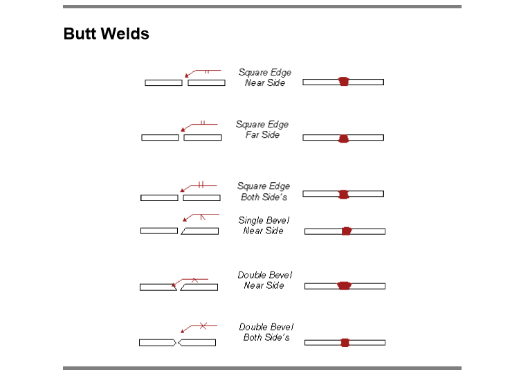
The following illustrations show simple weld symbols and the resulting application.


Deciphering Weld Symbols
When welds are specified on engineering and fabrication drawings, a cryptic set of symbols issued as a sort of shorthand for describing the type of weld, its size, and other processing and finishing information.
The purpose of this page is to introduce you to the common symbols and their meaning.
The complete set of symbols is given in a standard published by the American National Standards Institute and the American Welding Society: ANSI/AWS A2.4, Symbols for Welding and Nondestructive Testing.
The structure of the welding symbol
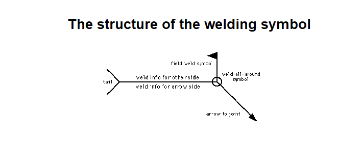

The horizontal line called the reference line is the anchor to which all the other welding symbols are tied.
The instructions for making the weld are strung along the reference line.
An arrow connects the reference line to the joint that is to be welded.
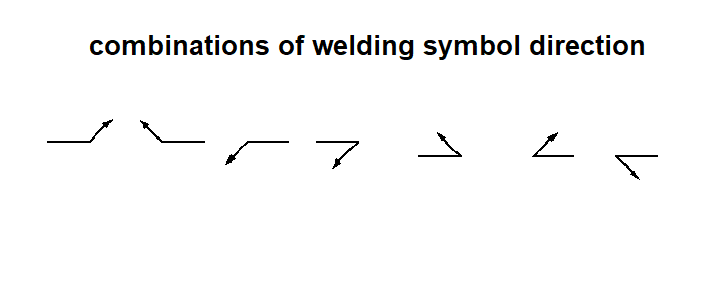
In the example above, the arrow is shown growing out of the right end of the reference line and heading down and to the right, but many other combinations are allowed.
Quite often, there are two sides to the joint to which the arrow points, and therefore two potential places for a weld.
For example, when two steel plates are joined together into a T shape, welding may be done on either side of the stem of the T.
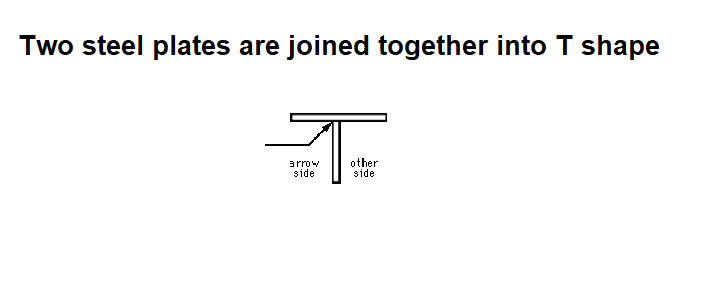
The weld symbol distinguishes between the two sides of a joint by using the arrow and the spaces above and below the reference line.
The side of the joint to which the arrow points is known (rather prosaically) as the arrow side, and its weld is made according to the instructions given below the reference line.
The other side of the joint is known (even more prosaically) as the other side, and its weld is made according to the instructions given above the reference line.
The below = arrow and above = other rules apply regardless of the arrow’s direction.
The flag growing out of the junction of the reference line and the arrow is present if the weld is to be made in the field during erection of the structure.
A weld symbol without a flag indicates that the weld is to be made in the shop.
In older drawings, a field weld may be denoted by a filled black circle at the junction between the arrow and the reference line.
The open circle at the arrow/reference line junction is present if the weld is to go all around the joint, as in the example below.
![]()
The tail of the weld symbol is the place for supplementary information on the weld.
It may contain a reference to the welding process, the electrode, a detail drawing, any information that aids in the making of the weld that does not have its own special place on the symbol.
Types of Welds and Their Symbols
Each type of weld has its own basic symbol, which is typically placed near the center of the reference line (and above or below it, depending on which side of the joint it’s on).
The welding symbol is a small drawing that can usually be interpreted as a simplified cross section of the weld.
In the descriptions below, the symbol is shown in both its arrow-side and other-side positions.
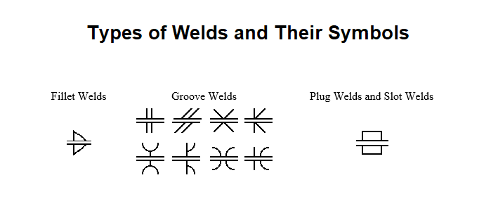
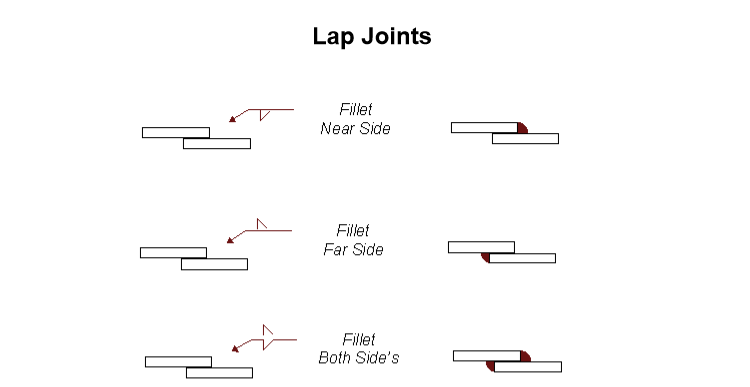
Fillet Welds
The fillet weld (pronounced “fill-it”) is used to make lap joints, corner joints, and T joints.
As its symbol suggests, the fillet weld is roughly triangular in cross-section, although its shape is not always a right triangle or an isosceles triangle.
Weld metal is deposited in a corner formed by the fit-up of the two members and penetrates and fuses with the base metal to form the joint.
The fillet weld symbol is one of the most widely used symbols and the shape placed on the reference line to indicate a fillet weld is a triangle that resembles the side profile of a fillet weld. The examples of the weld all around and field weld above show a fillet weld symbol so that the weld to be applied in both cases is a fillet weld.
Note: for the sake of graphical clarity, the drawings below do not show the penetration of the weld metal. Recognize, however, that the degree of penetration is important in determining the quality of the weld.

The perpendicular leg of the triangle is always drawn on the left side of the symbol, regardless of the orientation of the weld itself.
The leg size is written to the left of the weld symbol. If the two legs of the weld are to be the same size, only one dimension is given; if the weld is to have unequal legs (much less common than the equal-legged weld), both dimensions are given and there is an indication on the drawing as to which leg is longer.
The length of the weld is given to the right of the symbol.

If no length is given, then the weld is to be placed between specified dimension lines (if given) or between those points where an abrupt change in the weld direction would occur (like at the end of the plates in the example above).
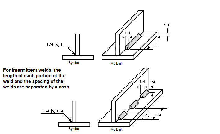
For intermittent welds, the length of each portion of the weld and the spacing of the welds are separated by a dash (length first, spacing second) and placed to the right of the fillet weld symbol.
Notice that the spacing, or pitch, is not the clear space between the welds, but the center-to-center (or end-to-end) distance.
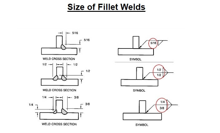
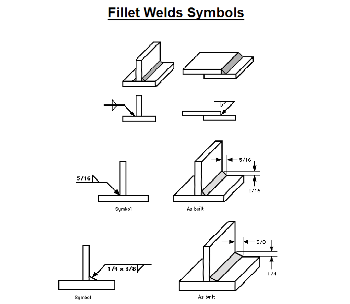
Size & Length of Fillet Weld
The size of the fillet weld is determined by the legs of the triangle shape which represent the legs of the fillet.
A welded piece may have a different weld size on each side or they may be the same size.
Sometimes (not often) a weld of unequal legs may be required.
For example: if one member of the joint is thinner than the other.
If no size is shown on the fillet weld, a size for all fillets will be given on the drawing as a note or specification.
The length of the weld when it is not a continuous weld is shown by a number on the right side of the fillet weld triangle. If it is not obvious the location is detailed on the drawing.
The Length and Pitch of Intermittent Welds
An intermittent weld is one that is not continuous across the joint, but rather is a given length of weld separated by a given space between them.
This method of welding may be used to control heat distortion or where the joint strength requirements allow.
Intermittent welding can save time and money if a long weld is not necessary.
Used more frequently than the length alone, the length and pitch are two numbers located at the right of the fillet weld symbol.
The length appears first as before followed by a hyphen then the pitch is shown.
The pitch refers to a dimension from the center of one weld to the center of the next weld.
The pitch is not the space between welds but a measurement from center to center of the welds. To get the spacing for layout subtract the length of one weld from the pitch.
The intermittent welds may be chain intermittent or staggered intermittent.
Chain intermittent the welds on both sides of the joint are opposite each other and resemble a chain.
Staggered intermittent the welds on the opposite side are usually started in the gap between the welds on the first side. The welds then appear staggered.
If the welds are staggered the fillet weld symbol will be staggered on the reference line.
Fillet Welding Symbols in Summary
When reading a fillet weld symbol always make sure you know what side of the joint the weld is applied to.
Fillet weld symbols on the bottom of the reference line mean apply the weld to the side of the joint the arrow points to. Fillet weld symbols on the top of the reference line mean apply the weld to the opposite side of the joint.
Fillet weld symbols on both sides of the reference line mean apply weld to both sides of the joint.
This remains the case regardless of how the break in the arrow is drawn.
The size of a fillet weld is determined by the length of the leg of the fillet weld and is shown on the symbol to the left.
If two numbers appear in parenthesis the legs are unequal, check the drawing for clarification.
When a length of weld is shown on a fillet weld symbol the dimension is placed on the right side. When two numbers appear separated by a hyphen, the length is indicated first then the pitch.
The pitch is the distance from the center of one length of weld to the center of the next length of weld.
When finishing directions are shown they appear over the slope of the fillet weld symbol.
For more information, see ANSI/AWS A2.4, Symbols for Welding and Nondestructive Testing.
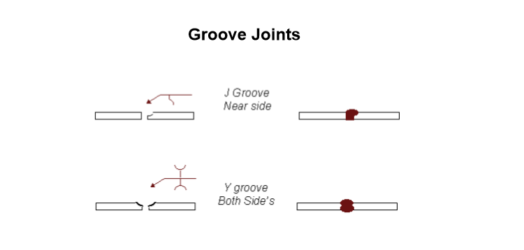
Symbols for Groove Welds
The groove weld is commonly used to make edge-to-edge joints, although it is also often used in corner joints, T joints, and joints between curved and flat pieces.
As suggested by the variety of groove weld symbols, there are many ways to make a groove weld, the differences depending primarily on the geometry of the parts to be joined and the preparation of their edges.
Groove welding symbols are used to show how butt joints are prepared for welding and to detail how the weld is to be applied.
When two pieces of metal, other than sheet metal or thin sections, are butted together for welding they usually have some form of a groove to allow the weld to penetrate into or through the joint.
The groove is formed by preparing the edges to be welded with a bevel edge, chamfer edge, double bevel edge, J groove edge or double J groove edge.
When the butt joint has no edge preparation it is referred to as a square groove.
Weld metal is deposited within the groove and penetrates and fuses with the base metal to form the joint.
Two other important elements for preparing and welding the groove are the root opening and the groove angle.
The root opening, when used, dimensions the space between the joint to be welded and is placed inside the weld symbol.
The groove angle is also placed inside the weld symbol and is given in degrees.
Note: for the sake of graphical clarity, the drawings below generally do not show the penetration of the weld metal. Recognize, however, that the degree of penetration is important in determining the quality of the weld.
The groove weld symbols are used to provide information for preparing and welding the groove; however, they cannot always show every intended operation and often notes or specifications are used on the drawing.
The welder should read the entire drawing before making a weld to avoid costly rework.
Whenever you see something you are unfamiliar, check with engineering or supervision for clarification.
It is critical to produce the right size fillet and groove weld for the application so check sizes with weld gages.
The various types of groove weld are:
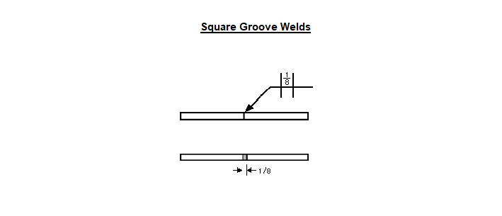
Square Groove Welds
The “groove” is created by either a tight fit or a slight separation of the edges. The amount of separation, if any, is given on the weld symbol.

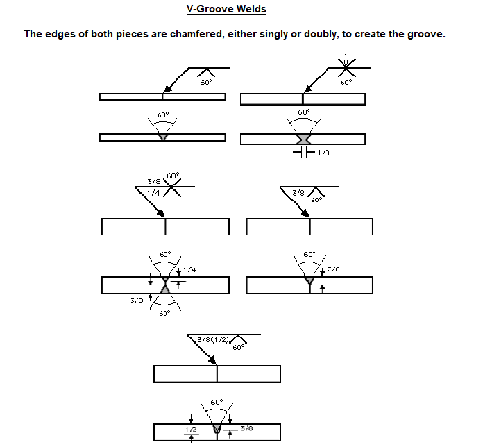
V-Groove Welds
The edges of both pieces are chamfered, either singly or doubly, to create the groove. The angle of the V is given on the weld symbol, as is the separation at the root (if any).
If the depth of the V is not the full thickness–or half the thickness in the case of a double V–the depth is given to the left of the weld symbol.
If the penetration of the weld is to be greater than the depth of the groove, the depth of the effective throat is given in parentheses after the depth of the V.

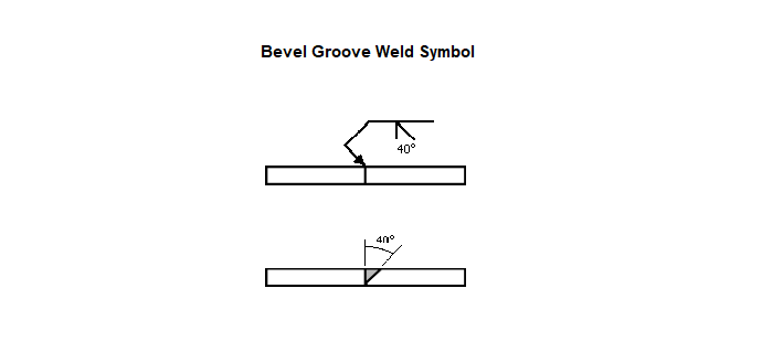
Bevel Groove Weld Symbols
The edge of one of the pieces is chamfered and the other is left square.
The bevel symbol’s perpendicular line is always drawn on the left side, regardless of the orientation of the weld itself.
The arrow points toward the piece that is to be chamfered.
This extra significance is emphasized by a break in the arrow line.
(The break is not necessary if the designer has no preference as to which piece gets the edge treatment or if the piece to receive the treatment should be obvious to a qualified welder.)
Angle and depth of edge treatment, effective throat, and separation at the root are described using the methods discussed in the V-groove section.

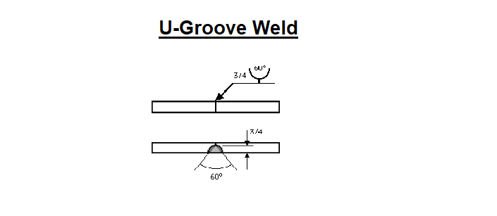
U-Groove Weld
The edges of both pieces are given a concave treatment. Depth of edge treatment, effective throat, and separation at the root are described using the methods discussed in the V-groove section.

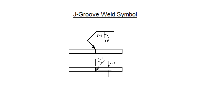
J-Groove Weld
The edge of one of the pieces is given a concave treatment and the other is left square.
It is to the U-groove weld what the bevel groove weld is to the V-groove weld.
As with the bevel, the perpendicular line is always drawn on the left side and the arrow (with a break, if necessary) points to the piece that receives the edge treatment.
Depth of edge treatment, effective throat, and separation at the root are described using the methods discussed in the V-groove section.
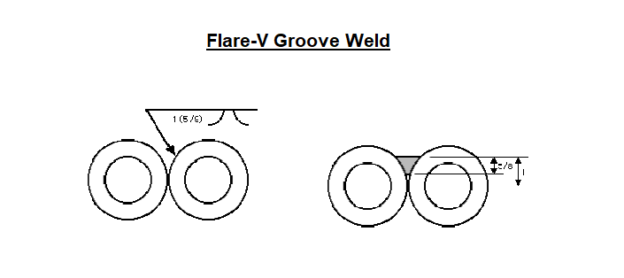
Flare-V Groove Weld
Commonly used to join two rounded or curved parts. The intended depth of the weld itself is given to the left of the symbol, with the weld depth shown in parentheses.

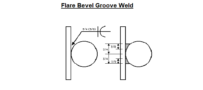
Flare Bevel Groove Weld
Commonly used to join a round or curved piece to a flat piece.
As with the flare-V, the depth of the groove formed by the two curved surfaces and the intended depth of the weld itself are given to the left of the symbol, with the weld depth shown in parentheses.
The symbol’s perpendicular line is always drawn on the left side, regardless of the orientation of the weld itself.
Common supplementary symbols used with groove welds are the melt-thru and backing bar symbols.
Both symbols indicate that complete joint penetration is to be made with a single-sided groove weld.
In the case of melt-thru, the root is to be reinforced with weld metal on the back side of the joint.
The height of the reinforcement, if critical, is indicated to the left of the melt-thru symbol, which is placed across the reference line from the basic weld symbol.
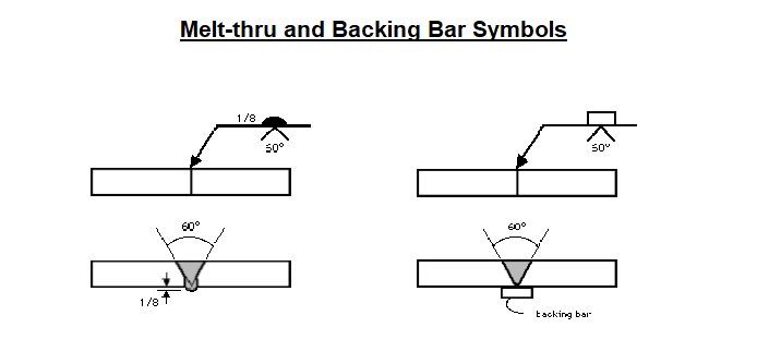

When a backing bar is used to achieve complete joint penetration, its symbol is placed across the reference line from the basic weld symbol.
If the bar is to be removed after the weld is complete, an “R” is placed within the backing bar symbol.
The backing bar symbol has the same shape as the plug or slot weld symbol, but context should always make the symbol’s intention clear.
For more information, see ANSI/AWS A2.4, Symbols for Welding and Nondestructive Testing.
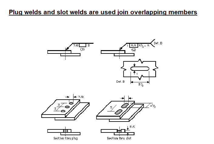
Symbols for Plug and Slot Welds
Plug welds and slot welds are used join overlapping members, one of which has holes (round for plug welds, elongated for slot welds) in it.
Weld metal is deposited in the holes and penetrates and fuses with the base metal of the two members to form the joint.
(Note: for the sake of graphical clarity, the drawings below do not show the penetration of the weld metal. Recognize, however, that the degree of penetration is important in determining the quality of the weld.)
For plug welds, the diameter of each plug is given to the left of the symbol and the plug-to-plug spacing (pitch) is given to the right.
For slot welds, the width of each slot is given to the left of the symbol, the length and pitch (separated by a dash) are given to the right of the symbol, and a detail drawing is referenced in the tail.
The number of plugs or slots is given in parentheses above or below the weld symbol.
The arrow-side and other-side designations indicate which piece contains the hole(s).
If the hole is not to be completely filled with weld metal, the depth to which it is to be filled is given within the weld symbol.