
Below is the list of tools and equipment that shall be required for installation of Synthetic Natural Gas SNG System.
Pipes and Tubes Cutter
Arc Welding Machine
Oxygen and Acetylene set
Calibrated Pressure Gauges
Standard Tool Kit for Welder
Standard Tool Kit for Welding and Brazing
Hand Tools (Wrenches)
Pressure Testing Pump
Pre Requirements
Check and verify that the approved shop drawings with correct revision are followed while taking up the work.
Materials are inspected by QA/QC for construction/installation purpose.
Ascertain that the area of installation is released by main contractor and stake locations of take off points from the sub-mains of the installed ring mains and isolation valves, where ever applicable.
Mark and line out route and locations of laterals lines, by co-ordination.
SNG Piping Installation Procedure
Ream pipe and tube ends. Remove weld splatters, scale and dirt on inside and outside before assembly.
Route piping in orderly manner, conserving building space and without interference with other systems.
Install piping to allow for expansion and contraction without stressing pipe joints or connected equipment as shown in the drawing.
Install exposed piping parallel or at right angles to the building walls, except where otherwise shown on the Contract drawings.
Where changes in the pipe size direction occur, install factory made tapered reducer fittings.
Where changes in pipe size direction occur, install factory manufactured fittings, bending and forming of piping strictly prohibited.
Provide adequate clearance o for installation of fittings and access to valves and fittings.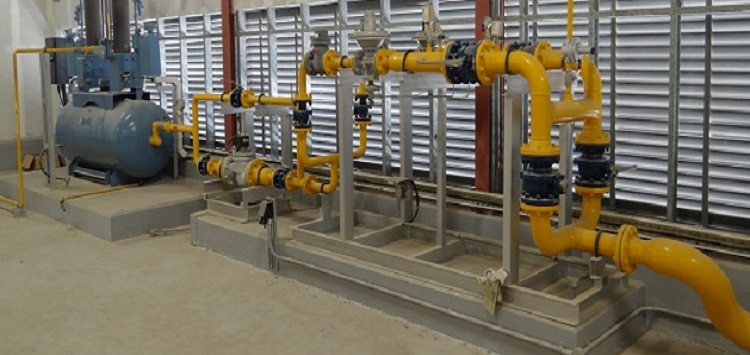
Provide minimum clearance of 30cm between piping covered by this section and those of other services.
Provide access doors where valves and other piping are located with distance not less than 30cm, all around.
All Exposed surfaces of pipe work, pipe support and brackets shall be painted by a 2 undercoated and 2 finishing coats.
SNG piping will be painted with a specific color different than other pipes.
A yellow color is recommended.
Valves should also be painted.
Direction arrows to indicate the flow of gas in the system will be painted.
Copper piping may be left bare, it is painted if required by the architect.
All exposed metal will be painted according to civil defense requirements.
Pipe Marking, Warning Boards to be provided as per local civil defense requirement.
Welding Procedure of Carbon Steel Pipes
The welding shall be done using the Shielded Metal Arc Welding (SMAW) process.
Joints shall be made by single or multiple pass welding, from one or both sides as per accepted WPS in line with specifications.
Preparation of Base Material
The edges or surfaces of parts to be joined by welding shall be prepared by oxy-acetylene machine cutting.
Where hand cutting is involved the edge will be ground to a smooth surface.
All surfaces and edges shall be free from fins, tears, cracks or any other defects which would adversely affect the quality of the weld.
All moisture, grease or other foreign material that would prevent proper welding or produce objectionable fumes, shall be removed.
Contact with lead, zinc, or lead or zinc compound shall be avoided due to the potential for hot cracking.
All surfaces to be welded shall be wire brushed prior to welding.
In multi-pass welds the weld bead shall be wire brushed between passes.
The brushes shall be of stainless steel and be kept exclusively for use on stainless steel and be kept clean and free of contaminants.
All other equipment such as grinding discs shall be kept exclusively for use on carbon steels.
Back gouging of welds shall produce a groove having a profile and a depth adequate to ensure fusion with the adjacent base metal and penetration into the root of the previously deposited weld metals.
Storage and Conditioning of Welding Electrodes
All electrodes shall be delivered in sealed containers that do not show evidence of damage.
Welding electrodes shall be stored in warm and dry conditions and kept free from oil, grease and other deleterious matter once they have been removed from their containers.
If reconditioning of electrodes is necessary, the electrode manufacturer’s guidelines should be followed.
Electrodes that have been wet shall be discarded.
Welding Position
The welding shall preferably be done in the flat position.
Horizontal, vertical and overhead positions may be also used with accepted WPDS/WPS.
Welding Technique / Procedure
The arc is initiated by quickly touching the tip of the electrode to the base metal and then quickly drawing the tip away.
Once the arc is established it should be kept short to ensure sufficient shielding by the molten slag, but the electrode should not be allowed to touch the molten weld pool.
Stringer beads are preferred over weaving to limit the heat input per pass.
Weaving may be used for welds in the vertical position, limiting the weave width to 2.5 times the electrode diameter.
A whipping technique should not be used.
All craters shall be filled at the end of each pass prior to breaking the arc.
Weld metal shall be thoroughly cleaned of slag and other debris prior to depositing the next pass.
To reduce distortion, use stringer beads at a higher speed rather than wide beads at a slower speed, or use rigid fixtures to hold parts in alignment or use backing bars to make cooling faster.
Arc strikes outside of the area of welds should be avoided on any material.
Use short arc length to prevent loss of Cr-Ni pick-up.
The size of any single-pass weld or the size of the first pass of a multiple-pass weld size shall be such as to minimize the possibility of cracking.
Prior to depositing weld metal on the underside of a welding groove, the root shall be gouged, or chipped to sound metal, unless otherwise specified on the applicable WPDS.
Larger size electrodes may be used for fill passes of the thicker material while smaller size electrodes usually applicable for root pass and/ or for thinner material.
Keep stainless steel materials clean and dry and keep them in separate place in warehouse.
Always use electrode size less than the thickness that you want to weld on.
Special ventilation and/or exhaust is required.
SNG / LPG Tank Storage Tank Installation
Storage, Loading and Transport
All necessary measures and caution should be taken into consideration to avoid any damaged to the tank, its painting and fittings, during storage, loading and transport.
Tank movements should be made using synthetic straps to avoid any damage to the tank painting.
The storage tank can only be moved empty, using the suitable lifting lugs.
Tank can either be supplied with its internal atmosphere inertized or filled with propane in gas phase (up to 0.5bar). Due to this, all necessary measures and caution should be taken into consideration during the tanks manipulation.
Tank Installation and Earth Connection
All legal and safety requirements of the country of installation should be taken into consideration during installation, which must only be performed by qualified personnel duly certified by local authorities, and contracted by the tank owner.
In underground tanks, earth connection is made through the anodes.
Resistivity between tank and soil should be lower than 100 ohm, or other value specified by any legal requirements of the country of installation.
If any small painting repair is required, due to any damage occurred during transport and installation, a paint repair kit is supplied with the tank.
Before any re-painting, the surface to be repaired should be duly sandpapered.
Excavation, and Burying the SNG / LPG Tank
Tank burying must be made with washed sand, without any kind of rocks.
During stage, all necessary measures and caution should be taken into consideration to avoid any damage to the tank, painting, accessories and cathodic protection.
Visual Control items before burying:
Painting control: scratches should not be visible.
Accessories box: any damage should not be visible.
Confirmation of the tank fixation to the foundation.
Confirmation of the stability and leveling of the tank.
Confirmation of electrical isolation of the tank.
Cathodic Protection of Tank Surface
Below instructions should be followed when mounting the cathodic protection:
- check the area near the tank for all possible causes of lost electrical currents that may cause malfunctioning to the cathodic protection.
- fully wet the anodes, before placing them on the ground.
- confirm the presence of the dielectric joint between the connection of the tank and the gas distribution net, to avoid electrical continuity between them.
- confirm there is no connection between the tank and any metallic object or structure near the installation area.
- After the anodes installation, four measurements at distinct places should be done to confirm the tank electric potential compared to a reference anode (Cu/Cu SO4).
- Minimum potential difference should be lower than -850mV.
LPG Pumps, Vaporizer & Blender and piping interconnection
All necessary measures and caution should be taken into consideration to avoid any damaged to the LPG pump, Vaporizer and Blender its painting and fittings, during storage, loading and transport.
Equipment movements should be made using suitable lifting equipment’s to avoid any damage.
LPG Tank to LPG Pumpset to Vaporizer and Blender:
Interconnection of LPG tanks to pumpset to a header that supplied liquid each vaporizer liquid inlet, SNG Surge tank outlet to Main Solenoid valve and to main distribution pipe line (Underground Polyethylene pipe) as per the approved drawing.
For interconnection piping refer to Welding procedure and to underground installation of PE Pipe.
Concrete for LPG Pump, Decanting pump, TTU, Vaporizer & Blender, ESS Nitrogen Station, Main solenoid valve and Vehicle Barriers:
Install all equipment on smooth, level concrete pad, designed to properly anchor and support the SNG equipment.
Concrete is typically formed 150mm beyond each edge of equipment skid base.
Provide a 25mm chamfer on all edges of concrete.
Anchor equipment as necessary to avoid movement or damage to piping.
Gas Isolating valves, Solenoid Valves, Gas Regulator & Gas Meter in Kitchen / Boiler (1st & 2nd stage)
Provide Isolating valve in the upstream of the solenoid valve.
Solenoid valve should be provided in upstream of the regulator.
Gas meter should be installed in the downstream of the regulator.
Isolating valves should be provided in each dropper in the kitchen.
Additional isolating valves should be provided in each equipment connection.
Flexible connection will be provided by the equipment supplier.
Distribution Station
Distribution station is the overall shut down station of SNG system in the SNG network.
It is the main control of SNG system in order to shut down in case of gas leak or fire.
Distribution station is composed of the following:
- Isolating valves at upstream and downstream
- Gas filters (two stream)
- Main Solenoid Valve
- By pass valve for solenoid
Gas Leak Detection System
A gas leak detection system will be installed to monitor for gas leaks at different location of gas network.
Gas sensors will be located as follows:
- One, on each LPG tanks
- One, on LPG pumpset
- One, on LPG vaporizer and blender
- One, on distribution & main solenoid
- On kitchens and boiler as per approved drawings.