
Before understanding the important factors related to welding joint design, please note that apart from resistance spot welding (RSW), three processes are most commonly used for welding metal stampings and fabrications:
gas metal arc welding (GMAW) or MIG;
gas tungsten arc welding (GTAW) or TIG; and
gas welding.
Although a high initial investment is necessary, additionally laser welding is being more widely employed by companies requiring large quantities of multi-point welds.
This method employs robots, welding at speeds of up to 150 inches (3.8 m) per minute. Other processes plasma arc, ultrasonic, and electron beam welding are also available, but these methods are usually restricted to welding of particular materials with special design requirements, such as microelectronic and aerospace components. Suitability of these methods for general sheet metal applications is limited, and processing may be cost-prohibitive.
Gas metal arc welding
This method is commonly called MIG (metal inert gas), the process creates an arc between a continuous wire filler metal (consumable electrode) and the sheet metal work pieces.
Shielding gas protects both the molten metal and the arc from the atmosphere. This process is suitable for most metals and alloys.
Among the most readily weldable materials are:
- carbon steels,
- low-alloy steels,
- stainless steel; 3000, 5000, and 6000-series
- aluminum alloys; and
- magnesium alloys.
Other alloys that can also be MIG-welded via special methods include 2000 and 7000-series aluminum alloys; high-zinc-content copper alloys, and high-strength steels.
Gas tungsten arc welding
Commonly called TIG (tungsten inert gas), produces an arc between a non consumable tungsten electrode and the sheet metal work pieces.
Inert gas is used to shield the arc and the work; filler metal is optional. Like MIG, TIG can be used to join most metals and alloys, but produces higher quality welds because of the absence of weld spatter.
Unlike MIG, TIG can be used to produce fuse-welded joints without filler metal, resulting in minimal eruption above the base metal.
Tig welds can be made in all positions, but the process is considerably slower than other welding processes.
Compared to MIG, TIG typically takes a minimum of twice as long to complete the same type of weld. Pulsed current is a TIG variation, which can reduce distortion in sheet metal and more easily accommodate a less-than-optimum fit of parts to be welded.
Oxyfuel gas welding (OFW)
This welding technique makes use of the heat generated by an oxygen and acetylene gas (or other gas) flame to weld two components together. Filler metal is supplied by a welding rod.
This method is declining in use because of heat distortion, and because faster more economical methods are available.
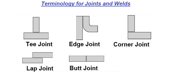
Welding Joint Design
Several types of joints can be appropriate for welded sheet metal design, among them are butt, corner, edge, lap and T-joints. In theory, types of joints do differ from types of welds. In practice, however the two terms are often confused.
The three basic types of welds are fillet, square and grooved.
Butt joint made on short-flanged edges requires no filler metal and helps control melt-through and distortion.
Lap joint with a double fillet weld should have a 1 in. (25 mm) minimum overlap. A single fillet and shorter overlap may suffice when less strength is required.
Compared to a single fillet, a T-joint with a double-fillet weld produces maximum joint strength. Shortest side of the fillet should be equal to the material thickness.
Corner-edge joints in thin sheet with a V-groove weld are completed with one pass. For higher strength, a second pass (inside) or backing may be required. A simple jig may be required to minimize distortion and maintain squareness of a corner joint.
For joints made on thin sheet certain dimensional recommendations or limitations apply to single-pass fillet and groove welds.
All types of joints–butt, corner, edge, lap and “T”–are appropriate for MIG and TIG welding. Corner joints, in particular, find extensive use in sheet metal cabinets and enclosures.
Importance of Specifying Welds
To avoid extra cost and excessive part distortion, the knowledgeable designer avoids over-specifying welds.
In structural or dynamically loaded parts where strength and performance are important, the welding method is usually specified.
In statically loaded parts like cabinets, the method is not as critical, because service loads are relatively small. With a tack weld, for instance, length of weld, size, spacing, location and frequency (number of welds) are typically specified, but not the method.
When welds are specified on an engineering drawing, they are often done “by the book,” following ANSI/AWS A2.4-79.
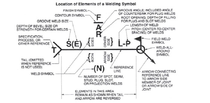
Although technically correct, following this method may generate many extra hours in part design.
Usually it is sufficient to designate welds with notes on the drawing without separately calling out fillet welds, groove welds, etc. This is particularly applicable to welding sheet metal parts when the same process is used to make all welds.
Some metal forming suppliers suggest that designers not specify the exact method and type of welding. This provides increased flexibility, depending on the equipment available, and often results in the most economical choice for the customer.
For covers and decorative items, it usually suffices to specify “corners must be filled or smooth,” or alternately, to reference a paint or other finishing specification, which simply may designate “no openings.”
Similarly, chassis design merely requires specifying weld location, leaving the welding method up to the supplier.
For welding corners on a frame or similar component, MIG welding is structurally sound and the surface can be readily ground to produce an acceptable surface for painting or other finishing.
When welding covers and other cosmetic parts, TIG welding with a filler wire often delivers the best economy.
Tack welds are often used to hold parts in place while more extensive, final welds are made. For sheet metal, tack welds often provide more than adequate strength and avoid the over design and expense of an “all-around” fillet weld. However, if no other welding is required on an assembly, spot welding deserves initial consideration.
Impact of Material Thickness on Welding Design
Because of the flexibility of arc-welding processes, thin sections can be joined to thicker sections more readily than with resistance welding. Optimum weld quality results when the workpieces being joined are approximately the same in thickness, thus allowing for equal weld penetration during fillet and tack welds.
General guidelines are helpful: MIG with short-circuiting metal transfer is recommended for steels from about 0.250 in. (6.35 mm) thick down to about 0.020 in. (0.51 mm).
The pulsed arc method is appropriate for sheet down to 0.048 in. (1.22 mm). In contrast, TIG can be used to weld sheet as thin as 0.005 in. (0.13 mm).
Weld Strength
In theory, weld strength should be adequate to handle the stresses the assembly will see in service plus the desired safety factor. Yet over design of specified welds is common. A weld may be over designed to boost the strength of a thin sheet metal part (designed thin for cost saving), but final cost may surpass that of using heavier gauge metal in the first place.
The metal forming supplier can often help determine the best welding option based on manufacturing capabilities and experience.
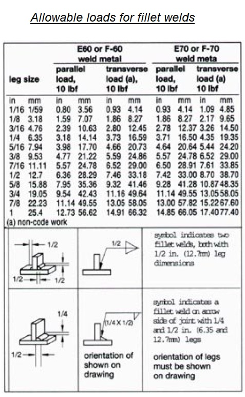
A weld can never be stronger than the base metal. For welded butt joints, strength is usually equal to that of the base metal. For fillet welds, stresses are assumed to act in shear and weld strength depends on leg size, length of the weld, type of weld metal, and loading direction.
Cost of Welding
Because welding is such a versatile process, it is often the best way to produce sheet metal assemblies which must meet both strength and cosmetic requirements. However, compared to other joining processes, manual welding, particularly in smaller volumes, can be relatively expensive.
As the volume of the product to be assembled increases, the process becomes competitive with alternate joining methods. High volume products can be very economically produced using dedicated fixturing and laser, semiautomatic or robotic welding techniques.
The length and width of a weld can have a great effect on cost. By not specifying size, length and number of welds, and by avoiding fillets that are welded all around, the size of a weld can be limited, reducing cost.
Additionally, choosing weld locations and orientations that more directly resist primary service stresses can reduce weld size. Again, this reduces labor and material costs.
Welding Finish and Spatter
If a perfectly smooth surface is required, MIG welding is not the method of choice because it generates spatter. Designers should be careful to specify when weld spatter is not allowed.
Table I. Allowable loads for fillet welds.
As an alternative, if the weld can be put on the inside of the part and spatter is acceptable there, design requirements can be met most economically with MIG, because it is much faster than TIG. Occasionally, both TIG and MIG welding may be used to obtain optimum cost-effectiveness and meet cosmetic requirements.
If parts have to be masked for spatter, or cleaned after welding or if anti-spatter compounds are required MIG costs can increase dramatically, making TIG welding more cost-effective.
Parts that are to be painted or otherwise finished after welding may require a secondary grinding operation to smooth welds down to an acceptable level. Depending on finishing specifications, the cost of secondary grinding can easily equal or exceed the initial welding cost.
When welding is done on a “face” or cosmetic panel, small dips or undercuts may appear. If this is visually unacceptable, grinding and polishing are needed.
Surface finish should always be specified to reflect cosmetic requirements. This is particularly important when welding thick to thin material.
Understanding the Weldable Materials
MIG and TIG processes can weld practically all ferrous and nonferrous materials to themselves or to very similar alloy compositions. For welding dissimilar metals, TIG is the process of choice, permitting carbon steels to be joined to stainless or to copper alloys.
Before opting for such designs, however, consideration should be given to consequent effects, such as galvanic corrosion and differences in expansion coefficients and conductivity.
Welding dissimilar metals requires special attention to electrode composition, welding technique, and other factors, and involves additional cost.
Steels coated with cadmium, lead, tin and zinc present special problems in achieving a sound, cost-effective and cosmetically acceptable weld.
In all cases, toxic gases are produced. Even aluminum-coated steel presents difficulty and requires special methods.
Further, when coatings are removed to facilitate welding, they usually must be reapplied afterward at additional cost.
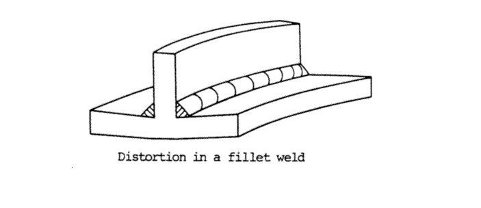
Handling the Weld Distortion
Distortion can be a major factor in sheet metal welding. Whenever sheet metal is heated, some distortion will occur.
In general, distortion can be controlled to varying degrees by clamping or fixturing, use of heat sinks and special welding techniques.
Proper joint design and correct welding procedures limit distortion.
Certain welding configurations are more likely to distort. For example, welding four corners on a cover or enclosure usually produces distortion. The more welding done, the more distortion will occur. Even tack welds create distortion, which can be minimized by careful spacing.
The American Welding Society (AWS) recommends 2 in. (51 mm) as a minimum between tack welds.
While special weld techniques and welding sequences can be used to minimize distortion, avoiding distortion completely can be very costly and very difficult to ensure. The cost-effective approach is to permit a certain amount of distortion and allow for it in part design.
Distortion of local features can also be a problem. In a flat plane, local distortion is likely if other design features are too close to the weld.
For instance, holes located 1/4 in. (6 mm) from the weld will change shape. Consequently, secondary operations like reaming, drilling or punching after welding, may be required to restore function. Prediction of heat zone distortion usually requires trial and error experimentation before completing a design.
Good Fit-Up for Quality Welds
Fit-up, or how well components line up, can have a dramatic effect on weld quality and generally depends on the material thickness and how parts are welded. A large gap between parts will cause shrinkage upon cooling and produce excessive distortion or result in burn-through. Tight fit-up is a prerequisite for quality TIG welding. This is most important when fuse welding without filler metal.
Importance and Effect of Fixtures and Tooling Holes on Welding Joints Quality
Tooling holes or other self-locating features on parts being welded into an assembly are of utmost importance and should therefore be part of the original design whenever possible.
The significance of these features is the economical and quality impact they have on the finished product. This is especially true for smaller, close tolerance assemblies.
The use of welding fixtures is sometimes unavoidable and even dictated by circumstances, but do add an initial tooling cost to the project. Fixtured assemblies are also slower to work with than self-fixturing features because of added bulk weight, which adds to the per-part-cost.
Since fixtures have tolerances of their own, and gauging contacts, clamping pressures and deflections can vary from part to part, the tolerances of the welded assembly will reflect these variables.
The great variety in size and accuracy requirements of welded assemblies dictate different methods of fitting and fixturing.
Exacting electronic housings, for example, need a different approach than a heavy wall and angle iron structure. With this in mind, the design tolerances should be based on material thickness, structure size and welding process.
Weld Location and Accessibility
Welds must be located with operator accessibility in mind. While it’s very simple to indicate a weld on a drawing, accessibility requires careful planning. Most welding processes are limited by the torch size and the angle at which the electrode is applied to the work.
In practice, MIG torches take up more space than TIG torches, but in either case, the operator needs room to access the joint. If accessibility is doubtful, check clearances with the metal forming supplier before the design is finalized. See Figure 9 for various design geometries that should be avoided.
The Cleaner, the Better
To achieve optimum quality welds, workpieces should be free of foreign contaminants, oil, grease, etc. In general, cold-rolled steel parts require little cleaning, while hot-rolled steels may require special cleaning. Aluminum alloys require wire brushing or etching before welding to remove oxidation and produce the highest quality welds, at added costs.
Defects That Can Affect Quality
Rejections most frequently occur because of distortion caused by the cooling of the weld metal and resultant pulling on adjacent parts.
In applications where all the special techniques available to a welder are used, the part still may not be flat after welding without use of a secondary straightening operation. Such extra-cost secondary operations should be weighed against more liberal flatness requirements, such as 0.008 in. (0.20 mm) per linear inch of surface.
Finishing Considerations
It is extremely important that the designer consider the effect of any welding on subsequent finishing operations. Welded assemblies to be painted should preferably be designed with hidden welds. If this is not possible, locate the welds for easy and economical grinding access. Grinding should be avoided in inside corners or on internal surfaces, as it requires special equipment and costly hand operations.
Parts which are to be electroplated should be designed to eliminate overlapping seams, hidden corners and other areas where plating solutions can be trapped and create subsequent corrosion and bleed-out. Good welding design for finishing can be confirmed by consulting with the metal forming supplier early in product development.
Tolerance Considerations
Generally, weld length, height and spacing are not rigidly toleranced. These dimensions are usually toleranced very generously, and where possible, specified only by nominal dimensions. While elaborate fixtures can be used to control the length of a weld, this approach is expensive and slows down the welding process, further increasing manufacturing costs. Tolerancing the height of a weld within 0.030 in. (0.76 mm) will usually require a secondary grinding operation.
For economy, squareness also should not be over specified. When very accurate squareness is required, self-locating features should be incorporated, since this is much more cost-effective than building, using and maintaining a fixture. Self-fixturing assemblies can reduce the cost to fixture the components by as much as 60%.
Welding Automation
When part geometries, sizes, quantities, fit-up and fixturing are appropriate, processes like MIG, TIG and laser lend themselves to various degrees of automation, from semi-automatic to robotic welding. It should be noted that automated welding requires especially precise dimensional control of components, and may dictate special tooling.
If fixturing requirements permit, several parts can be ganged together, so that the robot can make identical welds on each part. The ultimate result is greater economy.
Pingback: Pipe Welding Procedure