
The purpose of this electrical works method statement is to establish a systematic and controlled procedure for the installation of Galvanized Iron (GI) conduit systems used for electrical containment works within the project.
By following this method statement contractor shall ensure that GI conduit installation activities are carried out safely, efficiently, and in compliance with approved construction drawings, project specifications, statutory regulations, and international standards.
Proper execution of the works will provide durable mechanical protection to electrical wiring systems while facilitating future maintenance, minimizing installation defects, and ensuring the overall reliability of the electrical installation.
This GI conduit method statement covers the complete installation process for GI conduits and accessories associated with low-voltage electrical systems throughout the project.
Scope of work includes receiving and inspection of materials, storage, setting out, conduit routing, cutting, threading, fixing, support installation, concealed and exposed conduit installation, installation above false ceilings, installation within blockwork and concrete structures, provision of pull boxes and junction boxes, bonding and earthing requirements, inspection activities, and pre-wire readiness verification.
The procedures outlined herein are applicable to all building areas unless otherwise specified by the project documentation.
Areas of Application
The GI conduit installation procedures shall apply to the following areas:
- Residential Buildings
- Commercial Buildings
- High-Rise Towers
- Hospitals
- Hotels
- Educational Facilities
- Data Centers
- Industrial Facilities
- Warehouses
- Utility Buildings
- Pump Rooms
- Electrical Rooms
- Plant Rooms
- Basement Areas
- Service Tunnels
- External Utility Structures
Related Standards and References
The execution of GI conduit works shall comply with the latest editions of the following standards and project documents:
- IEC 60364 – Electrical Installations of Buildings
- BS 7671 – Requirements for Electrical Installations (IET Wiring Regulations)
- NFPA 70 – National Electrical Code (NEC)
- BS EN 61386 – Conduit Systems for Cable Management
- IEEE Standards where applicable
- ISO 9001 – Quality Management Systems
- ISO 45001 – Occupational Health and Safety Management Systems
- Approved Shop Drawings
- Electrical Layout Drawings
- Reflected Ceiling Plans
- Coordination Drawings
- Builder’s Work Drawings
- Approved Material Submittals
- Project Technical Specifications
- Inspection and Test Plan (ITP)
- Risk Assessment (RA)
Definitions and Terms
GI Conduit: A galvanized steel conduit used to provide mechanical protection and routing for electrical conductors.
Concealed Conduit: A conduit system embedded within concrete, masonry walls, slabs, or finishes.
Exposed Conduit: A conduit system installed visibly on walls, ceilings, or structural elements.
Pull Box: An accessible enclosure installed to facilitate cable pulling and maintenance.
Junction Box: An enclosure used to accommodate conduit terminations and cable branching.
Draw Wire: A galvanized steel wire or nylon cord installed inside conduits to assist cable pulling operations.
Roles and Responsibilities
Project Manager is responsible for ensuring the availability of adequate resources and manpower and monitor overall execution of works.
Construction Manager shall coordinate with other disciplines and ensure compliance with project schedules.
Electrical Engineer will supervise all the GI conduit installation activities and also verify compliance with approved drawings.
QA/QC Engineer will conduct routine inspections in order to ensure that quality requirements are achieved. Also make sure approval inspections are done as per the ITP and maintain inspection records.
HSE Officer is responsible to monitor safety implementation as per risk assessment, conduct toolbox talks and safety inspections.
Electrical Supervisor shall monitor and direct daily GI electrical works installation activities and shall allocate sufficient manpower and equipment as per site requirements.
Electricians and Technicians shall perform conduit installation works in accordance with approved procedures.
Necessary Materials
All materials used for GI conduit installation shall be approved prior to use, as per the approved material submittals. Supervisor shall make sure that all below mentioned materials are available for doing the installation of GI conduit works.
- Heavy Gauge GI Conduits
- Medium Gauge GI Conduits
- Flexible Metallic Conduits
- GI Couplers
- GI Elbows
- GI Bends
- GI Reducers
- Locknuts
- Bushings
- Spacer Bars
- Inspection Tees
- Male Adaptors
- Junction Boxes
- Pull Boxes

- Outlet Boxes
- Switch Boxes
- Back Boxes
- Adaptable Boxes
- Inspection Boxes
- GI Saddles
- Spacer Saddles
- U-Clamps
- Threaded Rods
- Unistrut Channels
- Angle Supports
- Anchor Fasteners
- Expansion Anchors
- Earthing Jumpers
- Earth Continuity Conductors
- Bonding Clamps
Mandatory Tools & Equipment
The following tools and equipment shall be arranged as per the site requirements:
- Conduit Threading Machine
- Pipe Vice
- Conduit Bending Machine
- Hand Benders
- Pipe Cutters
- Hacksaws
- Reamers
- Torque Wrenches
- Measuring Tapes
- Spirit Levels
- Laser Levels
- Marker Pens
- Rotary Hammer Drills
- Cordless Drills
- Grinding Machines
- Step Ladders
- Mobile Scaffolds
- Scissor Lifts
- Continuity Testers
- Earth Continuity Testers
- Measuring Instruments
All testing instruments shall be having valid calibration certificates.
HEALTH, SAFETY AND ENVIRONMENTAL REQUIREMENTS
Personal Protective Equipment (PPE)
All personnel shall wear:
- Safety Helmet
- High Visibility Vest
- Safety Footwear
- Protective Gloves
- Safety Glasses
Additional PPE shall include:
- Hearing Protection during cutting activities
- Dust Masks during chasing works
- Fall Arrest Equipment for work at height
Safety Measures
Manual Handling: GI conduits can be lengthy and awkward to transport. Team lifting techniques shall be adopted to avoid strains and injuries.
Cutting and Threading: Only trained personnel shall operate threading machines. Loose clothing and jewelry shall not be worn near rotating equipment.
Work at Height: Approved access systems shall be used. Ladders shall only be used for short-duration activities.
Housekeeping: Conduit offcuts, metal shavings, and packaging materials shall be removed regularly to prevent slips and trips.
GI CONDUIT INSTALLATION GENERAL ACTIVITIES
Ensure that the work area is ready and safe to start the installation of G.I. Conduits.
Ensure the installation of G.I. Conduits are carried out in accordance with manufacturer’s installation recommendations, requirement of applicable standards and in accordance with recognized industrial practices and specified in project specification to ensure that installation complies with requirements.
Prior to start the installation, refer to the approved shop drawings related to the area of installation and ensure that required materials are available at site as per approved material submittals.
Ensure the materials are stored properly and there is no mark of damage or deformity of any kind before issuing the material from site store. All materials and accessories should also be free of dust, scale, or oil.
Ensure that the issued materials are of approved specifications / submittals and as per the the requirement of the area shop drawing’s. (i.e. Make, size, Model / Type etc.,).
Site Engineer / Site supervisor has to ensure all civil works are completed for the area of installation and released / cleared by civil section to proceed on with GI conduit installations. Also the work area should be clean and safe to take up activities.
Mark and line out the route of GI conduit as per approved shop drawings with marking threads / marking powder.
Approved GI saddles shall be used at every 1200mm for fixing the GI conduit & 200 mm before pull box.
Ensure that junction boxes shall be used at every 10 mtr length of GI conduit and not more than 1 right angle bends allowed within this length.
Exposed threads of GI conduits shall be painted with zinc rich paint.
Sharp edges of GI conduit shall be filed to avoid damages to insulation of wires and painted with zinc rich paint.
GI conduits shall be connected with steel boxes, GI trunking, panel boards etc., using male brass bushes and serrated spring washers.
GI flexible conduits shall be used to take connections from un accessible location and end connections to motor terminal boxes. In damp areas like pump room and external areas, flexicon PVC covered GI flexible conduits shall be used.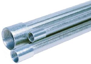
All pull boxes, junction boxes fixed on the wall with screw in the route of GI conduit shall be provided with GI cover after pulling the wires.
GI expansion couplers shall be used wherever GI conduit passes through building expansion joints
GI conduits shall be installed, concealed in building cladding or above suspended ceilings in finished areas and may be installed exposed only in unfinished areas.
Exposed GI conduits in unfinished areas shall be installed accurately in line and level.
Separate GI conduit shall be installed for each circuit and for each system of wiring.
Ensure that the Conduits are mechanically and electrically continuous.
Provide Earthing Terminals at each outlet box.
Ensure that the Conduits are cleaned and dry internally before the installation of wiring.
Ensure that the boxes and accessories in exposed or wet situation are made water tight.
Ensure that any damage to the finished is properly cleaned and painted.
Steps for Site GI Conduit Installation Work
Before commencement of work, the following checks shall be completed:
Documentation Review
- Approved drawings available at site.
- Material approvals obtained.
- Coordination drawings reviewed.
- Latest revisions verified.
Site Verification
- Structural works sufficiently progressed.
- Openings and sleeves coordinated.
- Ceiling levels confirmed.
- Conflicts with other services resolved.
Material Verification
- Correct conduit sizes available.
- Required accessories available.
- Materials free from defects.
MATERIAL RECEIVING AND STORAGE
Upon delivery, all GI conduit materials shall be inspected for compliance with approved submittals.
The inspection shall verify:
- Manufacturer identification.
- Conduit diameter and thickness.
- Galvanized coating condition.
- Quantity delivered.
- Availability of accessories.
Damaged conduits exhibiting excessive corrosion, deformation, crushed ends, or damaged threads shall be rejected.
Materials shall be stored in dry locations on elevated racks and segregated according to size.
SETTING OUT OF CONDUIT ROUTES
Accurate setting out is essential to avoid clashes and facilitate future maintenance.
The installation team shall:
- Review approved drawings.
- Mark conduit routes on site.
- Confirm outlet positions.
- Verify ceiling coordination.
- Check accessibility requirements.
- Obtain supervisory approval before installation.
CONDUIT CUTTING AND THREADING
GI conduits shall be fabricated using approved methods.
Procedure
- Measure required conduit lengths accurately.
- Cut conduits square using approved cutting equipment.
- Remove sharp edges using a reamer.
- Thread conduit ends using threading machines.
- Clean threaded surfaces.
- Verify thread quality.
Acceptance Criteria
- Threads shall be clean and continuous.
- No burrs shall remain.
- Conduit ends shall not damage cable insulation.
CONDUIT BENDING
Conduit bends shall be formed using approved bending equipment.
Requirements
- Bends shall be smooth and uniform.
- Conduit deformation shall not occur.
- Internal diameter reduction shall be avoided.
- Bend radius shall comply with specifications.
Factory-made bends shall be used whenever specified.
INSTALLATION OF EXPOSED GI CONDUITS
Procedure
- Mark support positions.
- Drill fixing points.
- Install anchors.
- Fix saddles and supports.
- Secure conduits.
- Align conduit runs.
- Tighten couplings and fittings.
- Install draw wires.
Acceptance Criteria
Exposed conduit runs shall appear neat, straight, level, and parallel with building lines.
INSTALLATION OF CONCEALED GI CONDUITS
Procedure
- Mark conduit routes.
- Prepare wall chases where required.
- Position conduits securely.
- Fix outlet boxes rigidly.
- Protect conduit openings.
- Verify alignment.
- Obtain inspection approval before concealment.
Acceptance Criteria
Conduits shall remain fixed during subsequent construction activities without displacement.
INSTALLATION IN CONCRETE SLABS AND WALLS
For conduits embedded within reinforced concrete:
- Coordinate with structural drawings.
- Install conduits before concrete placement.
- Secure conduits to reinforcement.
- Protect conduit ends against concrete ingress.
- Verify box elevations.
- Conduct inspections prior to casting.
Conduits shall not interfere with structural reinforcement unless approved by the structural engineer.
INSTALLATION ABOVE FALSE CEILINGS
Conduits installed above ceilings shall be independently supported.
Conduits shall not be supported from ceiling suspension systems unless specifically approved.
Adequate clearances shall be maintained from HVAC ductwork, sprinkler piping, and other building services.
INSTALLATION OF BOXES
Junction boxes and pull boxes shall be installed to facilitate cable pulling and future maintenance.
Requirements
- Accessible locations.
- Proper alignment.
- Correct mounting heights.
- Covers securely fixed.
- Identification labels installed.
EARTHING AND BONDING
All metallic conduit systems shall maintain electrical continuity.
Where required:
- Earth continuity jumpers shall be installed.
- Locknuts and bushings shall be tightened.
- Bonding conductors shall be connected.
- Continuity shall be verified prior to wiring.
DRAW WIRE INSTALLATION
Draw wires shall be installed immediately after conduit completion.
The draw wire shall:
- Extend through the full conduit length.
- Remain free from damage.
- Be securely fastened at conduit ends.
- Facilitate future cable installation.
INSPECTION AND QUALITY CONTROL
Inspection activities shall include:
Before Installation
- Material approval verification.
- Site readiness inspection.
During Installation
- Support spacing checks.
- Conduit alignment checks.
- Thread quality inspections.
- Box positioning verification.
After Installation
- Continuity verification.
- Draw wire inspection.
- Identification checks.
- Consultant inspection.
ACCEPTANCE CRITERIA
The GI conduit installation shall be accepted when:
- Approved materials are used.
- Conduit routes comply with drawings.
- Supports are secure.
- Bends meet specification requirements.
- Boxes are accessible.
- Draw wires installed.
- Earthing continuity verified.
- Inspection records completed.
- Consultant approval obtained.
TYPICAL SUPPORT SPACING REQUIREMENTS
| Conduit Size | Maximum Support Spacing |
|---|---|
| Up to 25 mm | 1.5 m |
| 32–40 mm | 2.0 m |
| Above 40 mm | 2.5 m |
Actual spacing shall comply with project specifications and applicable codes.
RECORDS TO BE MAINTAINED
- Material Inspection Reports (MIR)
- Inspection Requests (IR)
- Daily Progress Reports
- Conduit Installation Checklists
- Concealed Work Inspection Records
- Continuity Test Reports
- Non-Conformance Reports (NCR)
- Corrective Action Reports
- As-Built Drawings
- Final Approval Records
ATTACHMENTS
- Approved Shop Drawings
- Material Approval Documents
- Inspection and Test Plan (ITP)
- Risk Assessment (RA)
- Conduit Installation Checklists
- Concealed Work Inspection Forms
- Inspection Requests (IR)
- Continuity Test Reports
- Manufacturer Technical Data Sheets
- As-Built Drawings
CONCLUSION
The installation of GI conduits forms the backbone of a safe and durable electrical containment system.
Proper planning, coordination, fabrication, and installation practices are essential to ensure that electrical circuits remain protected throughout the service life of the building.
By adhering to this method statement, approved project specifications, and applicable international standards, the installed GI conduit system will provide robust mechanical protection, maintain electrical continuity, facilitate future maintenance, and support the successful execution of subsequent wiring activities while meeting the quality and safety expectations of the project stakeholders.