
1. PURPOSE
The purpose of generating this mechanical method statement is to define the procedure step by step to implement the correct practices for Installation, Pressure Testing, Insulation and cladding of Chilled Water Piping network including valves and accessories. Following the the guidelines contained herein shall ensure that the job execution complies with the project requirements and serves the intended function to a satisfactory level.
2. SCOPE
This Method Statement refers to various work procedures contained within project control documents, which explains and covers the Installation, Pressure Testing & Insulation of Chilled Water Piping including valves and accessories.
3. RESPONSIBILITIES
Site Engineer, Project In-charge (HVAC) / Foreman (HVAC).
4. TOOLS / EQUIPMENT
Fork Lift or Crane with capacity & arrangement in line with the Manufacturer’s recommendations, pallet mover and as required at site.
Hydraulic Trolley
Portable hand tools.
Portable Drilling Machine/ Grinding Machine & Angle Cutter.
Spirit Level / Level Threads
Step Ladder
Scaffolding with platform.
5. MATERIALS
Chilled Water Piping and accessories shall be in line with the approved material submittal.
Black Steel Pipes – up to 6″ dia ( Seamless as per ASTM A 53, Sch-40 )
Black Steel Pipes – Above 8″ (Seam less as per ASTM A 53, Sch-40 )
Fittings
Threaded Fittings up to 2″ ( ASME B 16.3 )
Butt Welded Type Fittings- Black Steel (ASME B 16.9) above 2″
Grooved Coupling joint type ( Only for risers & Plant room connection ).
Valves
Up to 50 mm : Thread ends
65 mm and above : Flanged ends
Accessories
Pressure gauges, thermometer, test points, air vents, etc.
Hanger & Supports
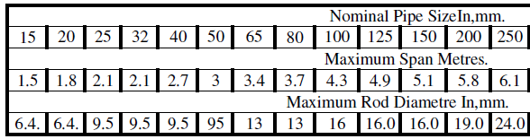
Hangers & supports spacing supports shall be as per specification
Horizontal Clevis Hanger or Trapeze Hanger
Vertical G.I Channel / Angle with U bolts & wooden block/Steel extension pipe-clamps. As per specification.
Maximum spacing between single pipe supports.
Horizontal piping support as shown as above hereinafter and at all change in direction.
Vertical support in side shaft at every floor level.
6. MATERIAL HANDLING & STORAGE
On receipt of the Chilled Water Pipe and accessories at site, necessary precautions shall be taken for unloading, shifting & storage, as follows:-
All materials received at site shall be inspected by consultant’s representative and to ensure that the materials are as per approved material submittals in terms of their make, model type, country of origin and capacity. Pipes must not be red oxide painted if not inspected by the consultant.
Any material while unloading shall not be dropped, but lowered to the ground.
Pipes shall be stacked on a flat surface with adequate supports.
While stacking, it shall be ensured that pipes of larger sizes are placed below and smaller sizes on top.
Stacked pipes will be protected by covering with tarpaulin sheet.
All other items such as valves, fittings, gauges, etc. shall be kept on racks within site stores and shall be segregated based on size, model, type etc. for easy retrieval.
Pipe insulation shall be stored in manufacturer’s packing in site stores.
Insulation material shall be segregated as per size, thickness for easy retrieval.
The adhesive material shall be stored in a covered and ventilated storage area.
All supporting materials shall be stored in a covered storage area, segregated according to size, type, model, etc. for easy retrieval.
Any items found damaged or not suitable as per project requirements shall be removed from site. If required to store temporarily, they shall be clearly marked and stored separately to prevent any inadvertent use.
7. INSTALLATION PROCEDURE GENERAL REQUIREMENTS
Check and ensure all drawings used for installation are latest and approved for construction.
Mark the pipe routing and support locations on the ceiling as per approved drawings.
Check the co-ordination of piping layout with other services and reflected ceiling and decide pipe route with minimum bends / offsets.
Check and ensure sufficient clearance around pipe is available for insulation.
Check the access and clear space around valves, vent points, drain points locations for maintenance and servicing.
Fabricate the structural supports from G.I. angles/channel as per support schedule as required.
After consultant or site engineer representative inspection. Prior to installation clean all pipes and apply primer / red oxide.
CHILLED WATER PIPES INSTALLATION PROCEDURES
Drill the holes in the slab / shaft for fixing supports.
Fix the anchors and threaded rods with hangers / structural supports as applicable. Threaded rod length shall be sufficient to allow for leveling of piping.
Cut the pipes accurately to measurements determined at site.
Prepare the pipe ends according to the type of joints i.e.. Threaded joints, welded joints / grooved coupling joints.
The end preparation shall be done at site work shop.
Threading & grooving as applicable shall be done as per fittings / couplings manufacturers recommendations.
End preparations for welded joints shall be done as per approved welding procedure.
After the end preparation clean the pipe ends and ensure no material and dust are left inside.
Qualified and approved welders by consultant shall be engaged in welding works.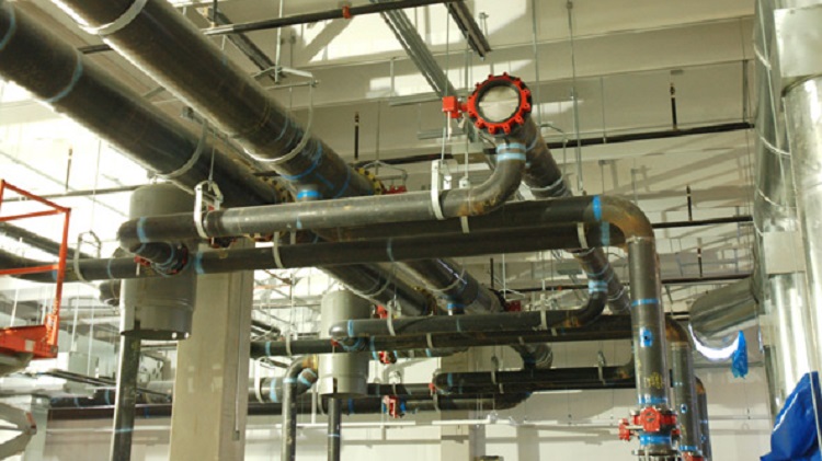
Install the pipe spools at heights as per approved drawings in a neat and tidy manner.
Insert the approved hard insulating material of suitable thickness between the pipe and support.
Align and level the piping as per approved drawings.
Install supports for horizontal and vertical as per schedule of supports.
Sleeves / openings of suitable sizes shall be provided at wall crossings.
Expansion couplers shall be installed at locations where piping crosses building expansion joints.
Install the piping connections with valves and accessories wherever equipment are installed.
For AHU’s and FCU’s, not installed, complete the by pass connections as per approved drawing.
Fix the blind plugs / temporary valves on all drain, air vent, pressure gauge, thermometer and test points tapings as applicable.
Check and ensure proper supporting is provided as per approved drawings.
Pressure Testing of Chilled Water Piping System
Make temporary tapping provisions at multiple points for easy and quick filling and draining of pressure testing water.
Ensure all joints are properly tightened.
During initial water filling, employ sufficient man power to monitor the entire length of the piping system for possible leakages.
If leakages are observed, arrest the leakages immediately. If leakages are major, isolate the leaking portion with nearest isolating valve and / or stop the water filling.
Ensure no leakages throughout the entire piping system.
Observe leakage and pressurize the system using hydraulic test pump.
During pressurization observe the joints and entire piping system for leakages.
Pressure the system till pressure on the pressure gauge at lowest part of the system indicates the 1.5 times the maximum working pressure of the system under testing.(100 psig/690kpa)
During hot ambient conditions system pressure may raise due to increase in the ambient temperature. Ensure under no circumstances the system is pressurized above 1.5 times the maximum working pressure.(100 psig/690kpa)
Observe the pressure gauge readings for 6 hours and ensure that there are no leakages.
The hydraulic pressure testing shall be witnessed by consultants.
Proceed with insulation only after satisfactory completion of hydro-static pressure testing.
INSULATION METHOD OF CHILLED WATER PIPES
For all pipe sizes, insulation pipe section of suitable thickness, as per approved drawings / submittals may be used.
Pipe surface should be cleaned and made free from dust and Grease. Insulation to be applied only when at normal temperature.
Adhesive of even coat is applied on the inner surface of the insulation section.
Pipe section is slipped over the pipe longitudinal joints of pipe section is sealed with an overlap of aluminum foil. Avoid longitudinal joints facing upwards.
Adjoining sections of insulation is butted firmly together by application of adhesive on the sides.
Cut slices of insulation and slip it firmly between joints to ensure tight packing of joints.
Seal all joints with aluminum tape.
INSULATION OF VALVES AND FITTINGS
Insulate valves, strainers, flanges and other fittings with identical material thickness and finish like the piping insulation
Fill all edges with filler sliced from the same insulation material and ensure no air gaps.
For site shaping of sections cut, scrape, or miter to fit contour of pipe fitting or valve.
For insulation of elbows cut one or more wedge shaped slices and fix firmly. Pack joints with slices of insulation.
When insulating flanges and flanged fittings the insulation cover to extend at least 50 mm onto the adjacent pipes to permit easy stripping of insulation to attend to valve for maintenance.
Insulate strainers to permit removal of mesh without disturbing the insulation of strainer
Vapor Barrier Application
- Apply a coat of vapor barrier solution (which can withstand up to 75% RH with a water vapor permeance of 1.3 perms at 0.031 inch dry film thickness) to the insulated pipe.
- Immediately embed the selected lagging fabric (8 oz canvas cloth/EQ) into the wet coating. Smooth to avoid wrinkles & overlap seams by at least 2 inches).
- Immediately apply a finish coat with the same vapour barrier solution.
- In areas subject to higher RH (more than 75%) like in air wells, roof etc. Apply a coat of weather proof coating with a very low water vapour permeability having a permeance of 0.05 us.
Note: To prevent fungal growth mix vapour safe coating with bison antifungal solution in proportion as specified by manufacturer.
- Ensure continuity of vapour barrier where pipe / duct supports are placed.
- At regular intervals use PVC isolators (circular strips of insulation size) to prevent moisture / water seepage through out, in case of accidental ingress of water in particular section.
- Clad the pipes if specified with aluminium sheet. Take adequate precaution to prevent the damage of vapour barrier while drilling / riveting.
- When insulation is done after pressure testing following procedure shall be followed.
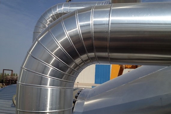
Cladding of Chilled Water Piping
- All external ceiling voids and plant room chilled water piping shall be cladded as per approved drawings and submittals.
- Aluminium sheets of approved type, quantity and thickness are cut as required and rolled in the rolling machine to give cylindrical profile and to form the longitudinal and circumferential groove.
- Slip the rolled aluminium profile on to the insulated pipe. Care shall be taken to ensure no damage to insulation.
- Match the longitudinal grooves of the rolled profile and join by GI/Aluminium pop rivets / stainless steel screws as applicable.
- The screw / rivets sizes shall be optimum, so that they do not pierce the insulation
- Fix the successive cladding and match the circumferential groove of previous cladding and fix screws / rivets.
- All longitudinal and circumferential joints are properly sealed using clear sealant.
- The valves, strainer NRV, flexible joints, pumps etc. are cladded by demountable boxes to allow maintenance access.
- Care shall be taken to ensure, the cladding surface is free from abrasion, scratches, dirt etc.
- Cladding shall be firmly fixed on the pipe.
- Raise the “Request for Inspection” for the inspection by consultant and obtain approval.
Raise inspection for Installation of Chilled Water Pipes, Fittings & Valves as per the approved project quality plan and ITP.
8. Health and Safety Requirements
- All safety precautions shall be followed as per established project safety plan.
- Warning signs shall be displayed while carrying out pressure testing.
- Only experienced and skilled technicians shall be engaged for carrying out installation and testing works.
- The people involved in the installation shall use PPE such as safety helmets, safety shoes, hornets, gloves etc. as required.
- Safety officer shall check and ensure that all safety precautions are followed.
- Safety officer shall check and ensure that all scaffolding and ladders used at site are having duly signed tags.
9. Attachments
Risk Assessment
Inspection and test plan ITP
Quality control procedure
Inspection Check sheet
Pressure Testing Check sheet