
The purpose of this mechanical HVAC method statement is to elaborate various work procedures which explains and covers the ductwork installation of HVAC Supply / Return / Exhaust Ducts, Dampers, Fire Dampers and Access Doors.
It is overall the responsibility of project HVAC engineer and his team to implement this duct work method statement, ITP and relevant checklists.
Below is list of mandatory tools required for the installation of HVAC air duct work:
- Portable hand tools
- Portable Drilling Machine/ Grinding Machine & Angle Cutter
- Rivet Gun
- Hammer Drilling Machines
- Hammer for driving anchor fasteners into structural membrane
- Wooden mallet
- Insulation cutting knife
- Spirit Level / Level Threads
- Step Ladder
- Scaffolding with platform
- Adjustable spanner
List of Materials for AC Duct Work
All the duct work materials and accessories shall be in line with the approved material submittals and project mechanical specifications. i.e.
- Factory fabricated ducts made of G.I Sheet as per SMACNA
- Threaded rods, & G.I. angle / Channel for supporting system
- Insulation as per approved submittal
- Duct liner adhesive as per approved submittal.
- Duct Sealant
- VCD’s, Balancing Dampers, Fire dampers, Motorized dampers and Access doors
AC Air Duct Work Material Handling & Storage
Duct pieces ( i.e. duct sections of Rectangular, Square, Circular ) C-cleats, S-cleats shall be fabricated in duct workshop as per approved material submittal, equipped with special purpose computer Numerical Controlled (CNC) machinery and special purpose tools.
All the duct sections shall be fabricated / joined as per SMACNA standard / design drawing details.
On receipt of ducts and accessories at site, necessary precautions shall be taken for unloading, shifting and storage, as follows:
Materials received at site shall be inspected randomly and ensure that the materials are as per approved material submittals.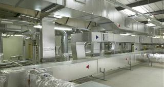
Any duct-works (Rectangular /Square/Circular) delivered at site shall be carefully off-loaded by deploying necessary / adequate dedicated manpower for loading and unloading materials in such a way that no damage is caused to duct-work.
Ducts & Accessories shall be stored in a place free of water, dust and adequately covered.
It shall be ensured that the fabricated duct pieces are numbered or tagged as per latest approved shop drawing to avoid wrong connections during assembly or installation and to expedite the progress in assembly works.
Duct Sealant and adhesive for duct liner shall be stored in enclosed area in closed cans as per manufacturer’s recommendations.
While unloading, shifting and storage, it should be ensured that there are no damages.
All insulation material shall be stored in a dry place and adequate cover shall be provided to ensure that they are not exposed to weather.
Any discrepancies, damage etc., found will be notified and reported for further action.
Material found not suitable for site use will be removed from site immediately.
Sequence of Work for HVAC Duct & Accessories Installation
Preparation:
The fabricated duct sections with proper identifications shall be received at site from work shop.
All received duct pieces will be segregated as per equipment / tag no.
On site assemblies & insulation shall be carried out at the designated areas at site near the vicinity of the area of installation of the ductwork system.
The outer as well as inner surface of each air duct shall be cleaned by cloth prior to installation.
Approved ac duct sealant shall be applied at the joints of the ductwork.
Two or more pieces of duct shall be joined together on the floor, to form manageable lengths.
Assembled duct sections (duct pieces) shall be insulated with approved insulation as per the specifications and approved material submittals.
Surface of the duct shall be cleaned with cloth to remove dust and debris and then proceed for insulation.
Insulation sheet of suitable thickness / length shall be cut to the size of duct to be insulated.
The insulation sheet shall be firmly fixed to the duct.
If any edge of the cut insulation sheet is visible the same shall be sealed .
All duct work joints shall be sealed with the approved duct sealant at site before joint insulation.
Horizontal Ductwork Installation Method
Prior to installation of ducts coordination with other trades / discipline will be done.
Position of duct supports shall be marked on the underside of the slab / structural member / vertical walls as the case may be and mechanical anchor fasteners shall be installed in slab or suitable clamps shall be installed if support to be taken from structural member, to facilitate suspension of threaded rods for duct trapeze support.
The support details and spacing shall be as per the approved drawings / schedule of duct supports.
Threaded rod of suitable size as per approved drawings shall be fixed to mechanical anchor fastener / clamps using proper lock nut.
G.I. Angle / channel, cut to required size of duct ( to have clearance of 50mm on either side after the insulation finish) shall be fixed to the threaded rod suspension and locked in position by suitable G.I nuts and washers.
Duct Pieces shall be installed and joined together as detailed on approved shop drawing.
Assembled ducts shall be lifted either manually or by mechanical lifting jacks required as per site conditions, and shall be installed on supports.
Similarly the next length of duct shall be installed and two are joined together by means of suitable C-cleats, S-cleats or flanges with gaskets and tied G.I nut bolts & washers.
The ducts shall be properly aligned and leveled to maintain B.O.D. and distances as per approved drawing.
Wherever branch take off collars are to be taken, suitable cut out shall be made in the ducts.
The size of cutout shall be equal to the duct cross sectional area and secured using aluminum pop rivets and the joint between collar flange and duct surface.
Ductwork Accessories Installation
Duct accessories such as volume control dampers, splitter dampers shall be installed as detailed on approved shop drawings.
Round Balancing dampers for final adjustment of flow, fabricated in workshop shall be installed at site as detailed in approved shop drawing.
Volume control dampers and fire dampers shall be installed at the locations shown on approved shop drawings and wherever required for balancing the system as per specification.
Joints of Volume Control Dampers (VCD’s), Fire Dampers and duct work shall be sealed with approved sealant.
Access doors shall be provided at all fire damper locations.
All insulated and uninsulated duct work passing through the openings in walls inside the building shall be provided with a G.I Sheet Sleeve
After installation of the duct work apply approved duct sealant to all flanged joints of the duct work installed by using sealant gun.
Flanges shall be clamped with nuts, bolts and cleats as required.
Duct joints, joints of branch tapping, butterfly dampers, volume control dampers, etc., shall be insulated with approved insulation.
Flexible duct connecters shall be provided at all locations where the ductwork crosses walls.
Ducts shall be connected to AHU’s & FCU’s with flexible insulated duct connectors.
Ducts shall be connected to Fans with flexible duct connectors.
After the alignment and leveling of ducts, the joints left without insulation shall be insulated with the insulation material as detailed above.
Threaded rods shall be cut to the size ( length ) for maintaining the levels of the approved shop drawing.
Duct work surface shall be cleaned with dry cloth to remove any surface dust and cut ends of angles & flanges which will be paint coated with zinc rich paint.
Vertical Ductwork in Riser / Shaft
Necessary scaffolding arrangement to suit site conditions shall be made by main contractor.
Duct supports shall be taken at each floor / vertical wall as the case may be and shall be as per approved drawings.
Suitable plenum box shall be connected to main duct through pre- insulated flexible ducts.
These diffuser plenums shall be prefabricated and shall be duly insulated and connect through round collars fixed to plenum.
Insulated flexible ducts shall be supported using 25mm G.I strip wound around the duct and suspended from slab for length 2.5 meter & above.
All open ends shall be covered & protected after installation of ductwork with polyethylene sheet.
Finally the insulated ducts are identified as per approved identification system.
All insulated ducts in the plant room and exposed to view shall be covered with aluminum cladding as per specification.
Acoustic Lining Installation Method
The inner surface of duct shall be cleaned by cloth prior to acoustic lining.
Approved Acoustic lining shall be provided inside the supply air duct for a maximum length of 3 meter from AHU / FCU with the help of adhesive and stuck-up pins.
Stuck-up pins shall be fixed to the inner surface of duct for acoustic liner.
Adhesive is applied on the inner surface and all over the periphery of duct.
Insulation sheet of suitable thickness shall be cut to the size of duct to be insulated.
The adhesive is allowed to dry for sometimes and the insulation sheet shall be firmly fixed to the duct.
If any edge of the cut insulation sheet is visible the same shall be sealed.
Vertical Ductwork Installation in Shafts
Prior to installation of ducts in shaft coordination with other trades / discipline will be done.
Necessary scaffolding arrangement to suit site conditions shall be made by main Contractor.
Duct supports shall be taken at each floor / vertical wall as the case may be and shall be as per approved drawings.
The support details and spacing shall be as per the approved drawings / schedule of duct supports.
G.I. Angle / channel, cut to required size of duct to have clearance of 50mm on either side.
Duct Pieces shall be installed and joined together as detailed on approved shop drawing.
Wherever branch take off collars are to be taken, suitable cut out shall be made in the ducts.
The size of cut out shall be equal to the duct cross sectional area and secured using aluminum pop rivets and the joint between collar flange and duct surface.
All insulated and un-insulated duct work passing through the openings in slabs inside the building shall be provided with a G.I Sheet Sleeve.
After installation of the duct work apply approved duct sealant to all flanged joints of the duct work installed by using sealant gun.
Flanges shall be clamped with nuts, bolts and cleats as required.
Duct joints, joints of branch tapping, shall be insulated with approved insulation.
All open ends shall be covered & protected after installation of ductwork with polyethylene sheet.
The insulated ducts are identified as per approved identification system.