
Below is a complete method statement for installation of cable tray, cable trunking and cable ladders in compliance with project specifications and approved material submittals.
Tool Required:
- Portable hand tools
- Portable Drilling Machine/ Grinding Machine
- Jigsaw Machine
- Spirit Level
- Level Threads
Material Handling & Storage
On receipt of the cable tray, trunking, cable ladder and accessories at site necessary precautions shall be taken for unloading, shifting & storage, as follows:
Material shall be stored in a covered / dry space at all the time to avoid corrosion.
All materials received at site shall be inspected to make sure that these are as per approved material submittals.
Any discrepancies and damages found will be notified and reported to consultant and supplier for further action.
Material found not suitable for site use will be removed from site immediately.
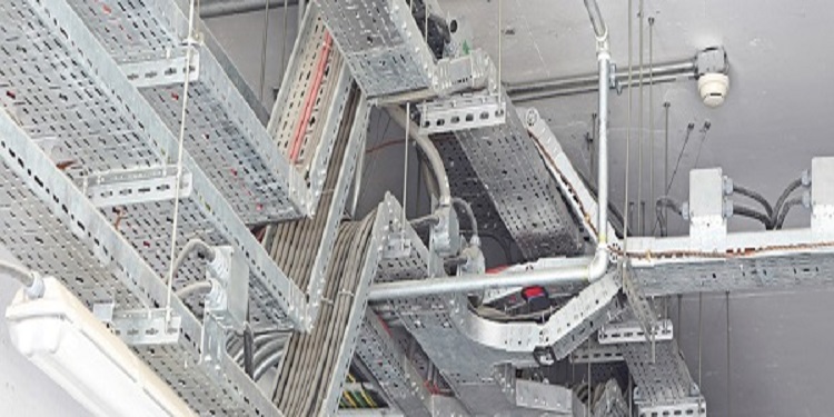
Cable Tray Trunking Installation Method
Ensure that the work area is ready and safe to start the installation of cable tray, trunking & cable ladder.
Makes sure that the installation of cable tray, trunking & cable ladder are carried out in accordance with manufacturer’s installation recommendations, requirement of applicable standards and in accordance with recognized industrial practices and specified in project specification to ensure that installation complies with requirements.
Prior to start the installation, refer to the approved shop drawings & coordinated drawings related to the area of installation and ensure that required materials are available at site as per approved material submittals.
Ensure the materials are stored properly and there is no mark of damage or deformity of any kind before issuing the material from site store. All materials and accessories should also be free of dust, scale, or oil.
Ensure that the issued materials are of approved specifications / submittals and as per the the requirement of the area shop drawing’s. (i.e. Make, size, Model / Type etc.,).
Site Engineer / Site supervisor has to ensure all civil works are completed for the area of installation and released / cleared by civil section to proceed on with cable tray, trunking & cable ladder installation. Also the work area should be clean and safe to take up activities.
Mark and line out the route of Cable Tray, Trunking & Cable Ladder as per approved shop drawings & coordinated drawings with marking threads.
Level threads shall be installed & adjusted to above the level of ceiling or drop beams wherever the trunking job is being carried out.
The route of Cable Tray, Trunking & Cable Ladder to be coordinated with other services.
Minimum space from the building structure and other services to be maintained to facilitate easy handling and maintenance of cables.
Supporting G.I channels shall be suspended from the sofit slab using GI threaded rods, GI washers and GI nuts at regular intervals not more than 1.2 mtr between the supports all as per the project specification.
Cable Trays and Trunking shall be fixed with metal bracket at an interval of 1200mm or less as per manufacturer recommendations and at 250mm from bends, intersection and termination points with GI Springs nuts and washers.
Expansion connections shall be made wherever Cable Tray and Trunking are crossing building expansion joints.
All straight joints, bends and offset connections shall be made neatly using manufacturer’s standard fittings. Only where these are inadequate fabricated one shall be used.
Cut portion of Trays and Trunking, GI channels to fabricate the required size and shape shall be made free of sharp edges and coated with zinc rich paint.
Tray and Trunking joints are to be positioned as close to the supports as possible.
Install 12.5mmx1.5mm copper earth bonding straps externally between all length of Cable Tray / Trunking & cable ladder and provide a copper bending straps across each joint; fixed with independent mushroom headed electro-plated bolts, nuts and serrated washers.
Ensure bonding of all the trays & trunking / tray systems are connected to main earthing system at the nearest point to the main earthing terminals.
Attachments
- Inspection and test plan
- Quality control procedure
- Check sheets
- Risk Assessment