
The purpose of this plumbing method statement is to describe the methodology for installation of booster pumps for cold water and to detail the steps to be taken to meet the HSE requirements specified for the execution of the project activities.
HSE Requirements
All personnel working at site shall attend HSE induction / awareness training programs conducted by the Safety Engineer / Officer.
Nominated supervisor will remain at site during the execution of the work.
Necessary safety precautions shall be implemented for all activities associated with electrical such as installation of electrical equipment’s and identified the materials as per the material data sheets.
PPE shall be worn at all times.
Safety Officer will remain present at site and will ensure that the provisions made in Project HSE Plan are complied with.
All necessary precautionary / safety measures such as putting warning tapes shall be taken to prevent any fall of persons into the pit.
Tools & Equipment
The job will be carried out by manual means. The following are the types of Tools identified for plumbing works:
Hand Tools;
Pipe Chamfering Tools;
Forklift
Drilling Machine 12” Capacity;
Mechanical Tool Box W / Tools;
Other necessary tools and instruments
Installation of booster pumps for Cold Water
Provide labor, materials, equipment and services, and perform operations required for complete installation of the booster pumps and related work as indicated on the drawings.
The work shall include, but not be limited to, the following:
Install centrifugal booster pump set as shown in the layout for water supply system.
The performance ratings of set shall not be less than those in the schedule.
Design shall consist of 2 or 3 multistage centrifugal vertical pumps assembled on a common base with inter connected piping for parallel operation.
The principal components of the booster and assembly shall be as detailed herein below:
The pumps shall be vertical multistage centrifugal with parts in stainless steel. The pumps shall be fitted with mechanical seal.
Motors shall be totally enclosed fan cooled direct coupled of standard version which shall dimensionally comply with IEC and DIN standards.
The maximum pumps speed shall be 2900 rpm.
Pumps shall be suitable for operation at 50 Degree C ambient temperature.
The motors shall be continuously rated with class ‘F’ insulation and IP 55 enclosure.
A diaphragm type pressure vessel is incorporated in the system.
It shall be constructed in the system and shall be constructed of welded steel, minimum 2 mm thickness suitable for the maximum working pressure.
The internal surfaces are coated with non toxic epoxy resin to prevent contamination.
A renewable butyl rubber diaphragm within the vessel shall separate air and water to avoid air absorption and eliminating the need of an air compressor.
The vessel shall be minimum 500 litters.
Interconnected pipe work shall be Electrophoresis treated steel with flanged ends for suction and discharge connections.
Isolating valves shall be fitted on either side of the unit and a non-return valve shall be fitted on the suction side of each pump.
The non-return valves shall of Cone type.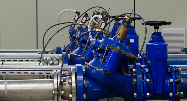
Each pump shall be fitted with a pressure switch.
Also a pressure gauge with gauge cock shall be fitted at the discharge side of the booster set.
Pump set shall be mounted on a base plate and shall be fully tested in the factory prior to dispatch.
The base shall be painted steel with vibration rubber isolations to arrest vibration transmission to the foundation.
Base frame shall be suitably anchored to the concrete foundation.
The assembly shall ensure that only simple connections of section, delivery and electrical power cable are only required on site to complete the installation.
Control panel shall be frame mounted heavy gauge cubical type.
It shall be a splash proof, dust proof enclosure finished in gloss enamel.
The door on the front side shall be lockable.
Enclosure shall house the following.
Hand/off/Auto SELECTOR SWITCH FOR EACH PUMP
Sequence Circuit
Control Circuit Fuse
Terminal Block
Main ‘ON’ indicator lamp
Pump running indicator lamp for each pumps
Pump ‘Tripped indicator lamp for each pump.
Control for operation in conjunction with float switches for low level control.
The float switches shall be installed in the storage tank.
Pressure switch for dry running protection (pressure switch shall be mounted on the common suction line for pumps).
Adjustable time for each pump
Low level protection indicator lamp, reset button and adjustable timer
Mains isolator fully interlocked with front cover.
Interlock facility with control for operation of the set automatically with BMS.
Alarm circuit with muting button.
MEP contractor shall be responsible for accurately checking all pumping heads, based upon the actual piping and equipment installation, and be responsible for furnishing pumps and motors of proper sizes for the actual service, regardless of those scheduled on plan.
Pumps shall be provided from the factory complete with their electric motors.
Piping shall be supported independently to prevent piping weight or stresses from bearing on or being transmitted to the pump.
Pumps shall be located in accessible locations for ease of repair and maintenance.
Pumps shall be constructed of specified materials and shall have pressure ratings suitable for the service and operating conditions.
Where there is a possibility of problems with corrosion, the appropriate corrosion resistant materials and assembly methods shall be used including isolation of dissimilar metals against any electrolytic corrosion.
Pump impellers and rotating assemblies shall be statically and dynamically balanced at the factory.
Booster pump sets shall be provided with plugged connections for vent, drain, and suction and discharge pressure gauges.
Low level float switches will be installed to provide power cut-off and prevent the running of the pumps.
Testing Requirements
Before operating and testing the booster pump, care shall be taken to ensure that pumps are properly lubricated, rotating elements, rotate freely, the casings are vented and full of water, the direction of rotation is correct, the strainers are clean and the suction and discharge valves are open.
Pumps shall operate stably without pulsation, vibration, noise or cavitation throughout their full capacity range.
Pumps shall be selected such as that operating levels of flow and head fall near the point of maximum efficiency as obtained from the manufacturer’s published data.
The horsepower rating of pump motors shall be of such magnitude as to ensure non overloading of the motor throughout the capacity range of the pump for the impeller diameter selected.
Electric motors shall always be specifically supplied for the available electric current characteristics of voltage and frequency.
Motor speed shall not exceed 2900 rpm.
The water will be kept in the system, or in the portion under test, for at least 15 minutes before inspection starts.
Correct all the defects detected by any test and retest the water supply piping system.