
Below is a brief safework method statement for bored piling that describes the whole construction procedures including material and equipment required for the construction of bored cast-in-situ piles.
Detail of the procedures contained herein maybe reviewed periodically and modified based on actual project site requirements.
The piles will be of a nominal specified diameter, bored through overlying soils to found in the bedrock strata or remain in the soil to act as shaft friction and end bearing piles.
Bored piles are designed by the engineer to resist axial compressive loads.
Construction Steps for Bored Pile
Pile boring operations shall be performed using the suitable rotary drill rigs depends on the diameter, depth, soil condition and construction method.
If necessary, the bore-holes shall be stabilized with a temporary casing in the upper layer (depends on soil and site condition).
The length of the casing will be determined from the actual soil condition encountered on site.
Bentonite shall be used for unstable subsoil condition and for piles equal and more than 1800mm diameter.
Pile Location Setting Out
The location of permanent bored piles shall be set out and pegged by the subcontractor’s surveyor based on approved setting out drawings from consultant and control points at site.
Surveying details of each location to be recorded incorporating reduced level and the coordinates.
Each individually surveyed pile position shall be protected from disturbance prior to commencement of boring works.
Two reference points to be installed equidistant at not less than 2 meter from the pile centre location.
A pilot hole of about 3-6 meter deep shall be drilled at the pile location.
The eccentricity and alignment of the pilot hole is then checked.
Pile Boring / Drilling Operation
Prior to commencing any drilling operations, the client representative will be required to verify all associated technical information such as presence of services, pile coordinates, platform and cut-off levels, validity of drawings etc.
Then, if necessary, after accurately setting out of the pile location by a land surveyor, a temporary casing will be set in position with length of casing to be determined from ground condition.
Vertical accuracy of the casing will be checked during the installation process using 2 numbers of plumb bob.
Excavation of the soil inside the casing/bored holes will be carried out using the rotary Kelly bar and the auger or bucket method.
The drilling process will be continued to the designed founding depth or to the commencement of rock head level by using augers and drilling buckets.
Pile lengths shall be as per the current construction drawings or as otherwise instructed by the client/consulting engineer.
At the point of encountering the rock (as define in the contract specification) head level, for examples, where the soil drilling tools are unable to penetrate the strata any further, boring shall cease in order that the client’s representative may verify the occurrence and confirm the rock socketing criteria.
For drilling through rock, rock drilling tools shall be applied. This shall include rock auger, core barrels, (round shank, roller bit) cross cutters and where necessary, chisels.
The final toe level of the pile shall be verified by the client’s representative.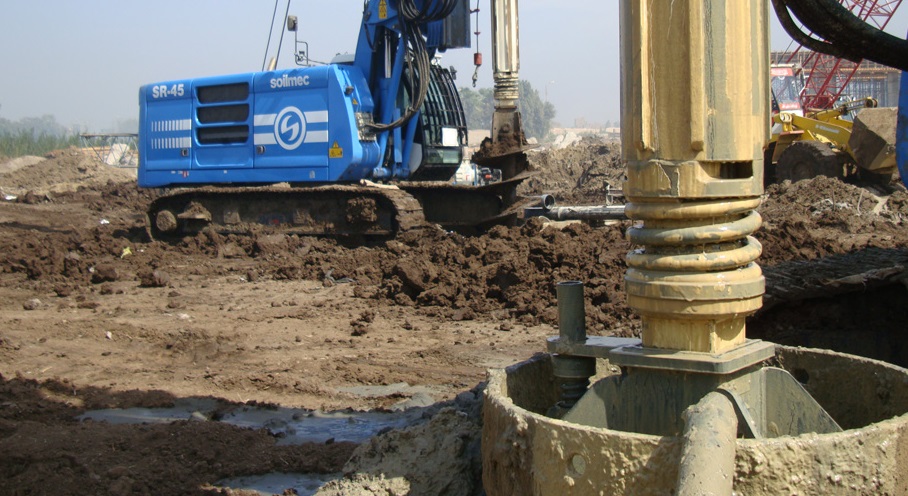
A detailed record of all encountered ground conditions together with the associated times and type of equipment and materials used will be recorded in the ‘Pile Bore Log’.
Upon reaching the final depth, loose and re-moulded material and debris will be removed using ‘cleaning bucket’.
The cleaning bucket is a specially designed flat bottom bucket which will pick up all the loose material at the bottom of the hole.
The base of the hole shall be checked by the measuring the depth of the base.
Application of Bentonite
The bentonite is delivered to site in 50kg per bags, which are stored under cover.
Bentonite is mixed by high turbulence mixers and the slurry is stored in a pool.
The size of the pool shall have a storage capacity of about 400 cubic meter.
A laboratory is provided on site for regular testing of the slurry.
Minimum frequency of testing and the acceptable range of physical characteristics of the bentonite slurry are given in project documents.
Laboratory reports are kept during the construction period.
Apparatus available in the site laboratory includes the following:
- 1 mud balance (density test)
- 1 marsh cone ( viscosity test)
- 1 sand screen set ( sand content test)
- Paper for measuring Ph
Contaminated bentonite slurry will be discarded by mixing with the earth and transport to dumping area.
Bentonite will be used as a drilling fluid to stabilize the bored hole.
During the boring process, the bentonite slurry is kept as high as possible within the casing and well above the existing ground water.
Upon completion of boring, the bottom of the bored hole is thoroughly cleaned with the cleaning bucket prior to recycling of the bentonite.
A submersible turbine pump attached to the tremie pipe is lowered to the bottom of the bored hole.
The bentonite, loaded with soil particles in suspension, is drawn off from the bottom of the bored hole and recycled through a recycling unit.
Recycling process is continued until the bentonite arriving from the base of bored hole had been flush out.
Steel Cage Installation in Bored Pile
Steel reinforcement cage will be fabricated in lay-down sections.
The length, type and size of the steel cage will be according to contract drawings and specifications.
Cages will be provided with stiffening rings and other accessories to enable handling, lifting and installation without permanent deformations.
Steel cages will be installed into the bored hole using a service crane of the required lifting capacity.
Concrete spacers wired to the cage shall provide lateral support and ensure adequate concrete cover.
Spacers shall be placed at 3 equal levels of each 12m cage with 3 numbers at each level.
If the diameter of bored pile is more than 2000mm the spacers shall be placed more than 3, to be advised by consultant representative.
Pile Concreting Using Tremie Method
All pile shall then be concreted by using the ‘tremie’ method.
Concrete of higher slump (=175mm+25mm) shall be used for ‘tremie’ method.
The self-compacting mixed concrete will be discharged through a tremie pipe, which is lowered centrally to the bottom of the bored hole prior to filling it with concrete.
Concrete level of the borehole to be recorded after each concrete truck discharge and graph will be plotted against theoretical.
One length shall be continuously embedded in the concrete during this process to ensure that the discharge of concrete is below the level of the impurities, which might be present in the top part of the rising head of concrete.
All testing and sampling of the concrete shall be carried out as instructed by the Engineer or Engineer’s representative.
A complete record of all cubes taken shall be maintained in a proper form and slump test results shall be recorded on the ‘Delivery Order’ and the ‘Pile Bore Log’.
All compressive concrete tests will be carried out at the supplier’s laboratory and independent lab.
The client will be notified of the dates of the test by regular issuance of notices in order the tests maybe witnessed.
For a continuous assurance of concrete quality and integrity, concrete will be poured to minimum 0.6m above the theoretical cut-off level.
All completed piles shall be temporarily barricaded and to be backfilled to ground level with a suitable material the next day.
Spoil Removal
Spoil from piles will be cleared from the boring locations by means of an excavator as boring proceeds.
Depending on the volume of spoil excavated, it will be removed to stockpile area or spoil pit, for drying before loading and removing from the site.