
If you want to learn high quality metallic pipe fabrication procedure then this page is best place to understand some mandatory requirements. This page contains information from different standards and may not be used as reference or basis for the welding or fabrication work at a project or at workshop etc. Information is shared for learning of the contractors, fabricators, installers and welders etc.
General Requirements:
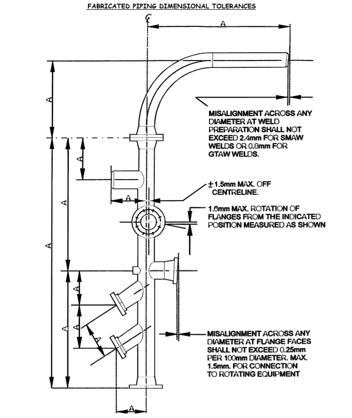
Where the butt weld ends of piping items are to be joined, accurate alignment shall be made within commercial tolerances (within 1.5mm).
If the wall thickness misalignment is greater than 1.5mm (1/16 in.) the heavier walled item shall be internally taper bored at 1:4 taper to give approximately equal finished wall thickness.
In No case shall the wall thickness be reduced below the nominal – mill under tolerance of the lower thickness pipe.
This misalignment tolerance is not permitted in piping to and from reciprocating compressors (through the second change in direction ) or in piping in severe cyclic conditions as defined in ASME B31.3. For such services, the inside diameter of the pipe shall be machined or ground to a close tolerance and the root pass shall be welded by the GTAW process.
When these two service conditions apply they shall be clearly stated on the isometric drawing.
Piping fabrication tolerances shall be in accordance with below figure, where the tolerance on linear dimensions indicated as dimension “A” shall not exceed 3.0mm.
Tolerances shall not be cumulative.
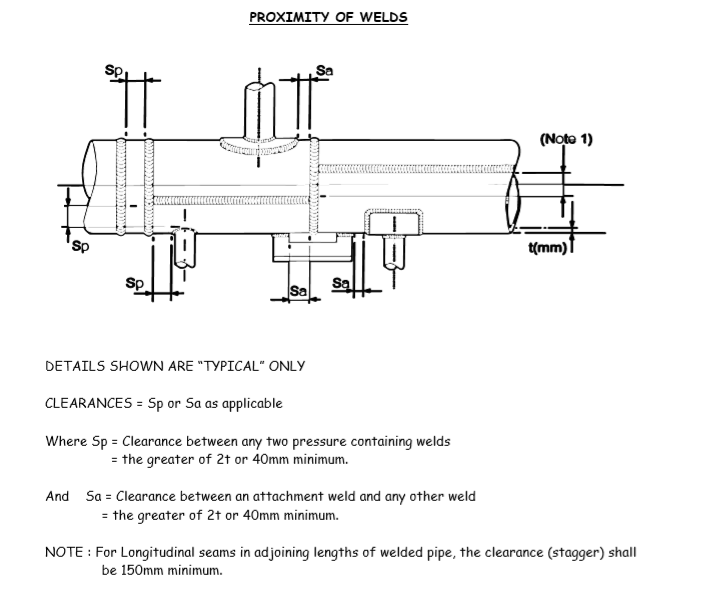
Longitudinal seams in adjoining lengths of welded pipe shall be staggered preferably 180o apart and shall be so located as to clear openings and external attachments. Clearance and stagger shall not be less than 150mm. Longitudinal seam welds shall be located in the top quadrant of the pipe wherever possible see figure below.
The toes of adjacent butt welds shall be no closer than two times the nominal thickness of the pipe with, in the case of NPS 12 and below, a minimum acceptable separation of 40mm. For pipe sizes greater than NPS 12 the minimum acceptable separation shall be 100 mm.
Branch and non pressure part attachment welds shall not cross longitudinal seams or circumferential butt welds and shall be subject to the toe to toe separation distance specified for circumferential butt welds.
Where such intersections are unavoidable the main weld shall be subject to non destructive examination prior to making the attachment weld.
Joints involving the intersection of more than two welds shall be avoided, see figure below.
Unless otherwise stated in the piping material class, fabricated branch intersections shall be of the “set-on” type with the branch pipe prepared to suit full penetration welding. Holes for branch connections shall be prepared by machine or flame cutting dependent on material except for holes less than 25mm nominal bore which shall be drilled. Flame cut edges shall be dressed to remove all oxide and dross.
Socket weld connections shall be made up with a 1.5mm to 3mm gap between the pipe nipple end and the counterbore shoulder of the fitting, good working practice would be to use spacers/washers.
The weld shall be a minimum of two passes to achieve the required throat thickness and leg length.
When used, pipe threads shall conform to ANSI/ASME B1.20.1. Threads shall be correctly formed and tapered and free from damage. When male and female threads are engaged and fully tightened to make a joint, the disengaged length of incomplete or vanishing thread shall be 2.5 times the thread pitch.
Seal welding of threaded joints, when specified , shall be performed only when the joint is made dry and is tight and all surface contaminates have been removed. All exposed threads shall be covered by the weld deposit with a minimum of two passes to ensure full fusion to the root of the thread. The welds shall be of good contour and free from undercut.
Where reinforcing pads are fitted, either for branches or structural attachment, they shall be accurately shaped so that no gap larger than 1.5mm measured before welding shall exist between the periphery of the pad and the pipe. The gap between the pad and the branch pipe should be kept to a minimum but adequate to allow access for welding and fusion to the parent pipe.
Openings for thermowells and other inserts shall be drilled through the connection after welding and should be free from obstruction.
For 300# rating and above, the misalignment between branch pipe/fitting bore and the parent pipe hole shall not exceed 1.5mm.
Weld neck orifice flanges shall be the same bore as the pipe to which they are attached and shall be accurately aligned. All internal weld protrusion shall be ground flush with the inside diameter.
All meter run lengths shall be good quality round and checked for ovality, no welds shall be present along the meter run length.
Seamless pipework 12” NPS and smaller may be fabricated using hot or cold formed pulled bends, where the bending radius shall not be less than 5 times the nominal pipe size. The bending and forming procedure including preheat and post weld heat treatment shall have prior approval from client.
Cold bending shall be performed at a temperature above the transformation range in accordance with the approved procedure.
Pulled bends shall be free from cracks, buckling, wrinkling, flattening and wall thinning. If flattening of any bend occurs it shall not exceed 5% of the nominal outside diameter of the pipe when measured by the difference of the maximum and minimum diameter at any cross section. The maximum decrease in pipe wall thickness shall not exceed 10% of the specified nominal wall thickness.
Temporary attachments to the outside surface of the pipe shall not be made without prior client approval. Any such attachments which are permitted shall be removed by grinding, followed by NDE (MPI or DPI dependent on material).
For all material grades other than PI all weld repairs shall be brought to the attention of the inspection agency.
For PI materials, which are in the PWHT, condition all weld repairs shall be bought to the attention of the inspection agency.
One repair attempt is permitted; if unsuccessful the repair shall be bought to the attention of the client / inspection agency.
Bend Preparation Procedure
Carbon Steel
Hot or cold formed pulled bends fabricated on site by the contractor in accordance with an approved procedure are acceptable with prior inspection approval.
Machine cutting is preferred but flame cutting and beveling is acceptable if the cut is smooth and true and all oxides are removed by grinding.
The flame cut shall be ground back 1.5mm to remove hard spots.
Low-alloy Steel
Hot bending of pipework shall only be performed off-site (workshop) under strictly controlled conditions to a procedure approved by client where:
a) The bending/forming temperature shall be 580 C to 750 C, and without cooling down to ambient temperature, thermally stress relieve at 720 C to 745 C. The holding time shall be half an hour per 13.0 mm of thickness for a minimum of half an hour, or alternatively:
b) The bending /forming temperature shall be 950 C to 1030 C followed by controlled furnace cooling down to 570 C and then cooling in still air.
The heating of the pipework shall be by the use of electric elements or full circumference gas rings. Local torch heating or quenching is prohibited with the exception in some conditions.
Machine cold cutting of pipe and of weld bevels is preferred but flame cutting may be employed providing that any cut edge is ground or machined back 4.0mm, with one individual 3.0 mm dimension, to sound metal.
All cut edges shall then be examined for cracks using dye penetrant or magnetic particle inspection. Any cracks shall be removed by grinding. Inspector may, at his discretion, allow the percentage number of cut edges being examined, to be reduced if the number of cracks found in the material are sufficiently few.
Bending Austenitic Stainless Steel
Cold bending is preferred but hot bending is permitted off-site (workshop) only, under strictly controlled conditions and to an approved procedure. The heating of the pipework shall be the muffle or semi-muffle type with accurate temperature measurement and control. Any contact with an open flame is prohibited.
The area used for fabrication needs to be totally segregated from the area used for fabrication of carbon steel and other low alloys steels. Adequate precautions need to be taken to prevent surface contamination by contact with jigs, vices and other fixtures manufactured in non compatible materials. Separate sets of clearly identified equipment i.e. grinding discs (s/s) files, wire brushes (s/s) need to be in place.
Cutting of pipework and weld beveling shall be machine cold cut or plasma cut.
Monel Bending
Hot bending of pipework is allowed under controlled conditions off-site (workshop) only to an approved procedure. Cold bending will only be permitted with prior approval. The hot bending temperature shall be 1010 C to 1175 C. The following controlled conditions shall apply to the heating medium (furnace atmosphere):
Localized heating for bending and forming is not permitted without prior client approval.
Where Monel is “worked” or “deformed” it shall be re-annealed in accordance with approved procedure/standard.
Cutting of pipework and weld beveling shall be machine cold cut or plasma cut. The weld bevel surfaces and adjacent areas shall be cleaned of all extraneous matter and any atmospheric oxide film on the surface.
The cleaning shall be carried out using a fine grinding wheel or disc followed by vigorous stainless steel brushing and finally solvent degreasing, this cleaning shall be carried out immediately prior to welding.
Nickel and Nickel Alloys
Hot bending of pipework is only permitted off site ( workshop), to an approved procedure, where strictly controlled furnace operation and conditions apply. The hot bending temperature shall be 1030 C to 1230 C. The furnace atmosphere shall be limited as follows:
Cold bending and localized heating for bending or forming will only be permitted with prior approval from the client.
Where Nickel or Nickel Alloy material is “worked” or “deformed” it shall be re-annealed in accordance with approved procedure.
Cutting of pipework and weld beveling shall be machine cold cut or plasma cut.
Immediately prior to welding the weld bevel surfaces and adjacent areas shall be cleaned of all extraneous matter and any atmospheric oxide film on the surface. The cleaning shall be performed using a fine grinding wheel or disc followed by vigorous stainless steel brushing and then solvent degreasing.
Metallic Pipe Assembly and Erection Guidelines
All flanged piping systems shall be assembled using service gaskets and stud bolts as detailed in the individual piping material specifications, except where line blinds are installed. At line blind locations non-asbestos gaskets shall be installed initially for hydro pressure test and shall then be removed and the correct service gaskets shall be installed.
All stud bolts shall be lubricated with high temperature lubricant; i.e. “Coppercoat” or equal, with the exception to the Alkylation Unit where Coppercoat is prohibited and a Nickel based lubricant should be used (i.e. Nickel Never Seize). For grade “8” austenitic stainless steel studbolts care shall be taken that the lubricant used does not contain chloride, sulphur or any low melting point metallic compounds. The studbolt shall have a minimum of two threads showing at each end without being too long. The contractor is responsible for ensuring joint integrity i.e. correct nuts, bolts, gaskets are used and that the joint is tight.
The assembly of misaligned pipework shall not be corrected by local heating, quenching or applying excessive force.
If “Cold Spring” is specified on the isometric or piping general arrangement drawings, extra care shall be taken with setting up, assembly and supporting of this pipework. Local heating shall not be used to aid erection.
Temporary and permanent supports shall be installed and spring supports shall be locked prior to hydro testing. Temporary welded supports are to be removed prior to hydro testing.
Spring supports shall be installed in accordance with spring support installation and commissioning specifications and standard. Note: After hydro-test all temporary supports shall be removed and the spring supports shall be released and commissioned in accordance with approved standards and procedure.
After hydro-testing where piping systems are required to be insulated and steam traced, certain corrosive services require the steam tracer to be clear of the process pipe to prevent “Hot Spots” or to prevent the process boiling ; i.e. Amine, Caustic, H2S etc.
All piping systems, after hydro-test, shall be left in the “ready for operation” conditions except for steaming through or flushing.
Where pipe spools are to be stored prior to installation, flange faces and pipe ends are to be capped and protected to prevent damage.
All pipework shall be identified by indelible marking, free from Sulphur, chloride and other halogens. For spools that will be subjected to post weld heat treatment a suitable titanium oxide pigmented heat resisting paint marker containing less than 250 ppm of lead, zinc or copper shall be used.
Vibro-etching techniques may be used for identification transfer, but adhesive tapes or hard stamping, other than with low stress stamps, shall not be used. Painted or corocoated spools shall have metal tags attached to the flanges for identification.
The marking applied shall identify the material and the fabricator and include an item or spool number enabling the spool to be traced to the relevant isometric drawing, sketch etc.