
Purpose of this mechanical safework method of statement is to ensure that correct materials are used and agreed procedures are implemented during fabrication, welding, installation and testing of the pump room piping network.
This method statement specifies the sequence and methodology for the installation and testing of piping to achieve the best quality of work.
General Requirements Before start of work in pumping room:
Cleaning all concrete inside selves and also on flanges.
Removing all remnants, scrap from the room.
Dismantle and remove all scaffolding from the room
Finishing all concrete base and inserting all guides for pump fixing by civil contractor and approval by consultant
Providing an electrical source inside the room (380 v).
Sample of pipes and fittings must be approved from consultant
Make sure that all and fittings are according to approved samples
Receiving all valves, flexible joints and all necessary fittings and accessories from the main contractor.
Store all materials in suitable storing areas.
Pumps Installation
Prior to start of installation it shall be ensured that the shop drawings including coordination drawings of the respective areas are approved.
Make sure that the area is released by main contractor to proceed with mechanical installations.
Ensure that all pumps are as per the approved material submittal and have been inspected & approved.
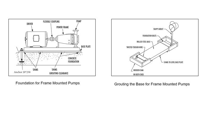
Ensure that the pump foundation is according to manufacturer’s recommendations and NFPA standards.
The foundation for pump must be sufficiently rigid to absorb any vibration and stress encountered during pump operation.
A raised foundation of concrete is preferable for most floor mounted pumps. The raised foundation assures a satisfactory base, protects against flooding, simplifies moisture drainage, and facilitates keeping the area clean.
Pump should be firmly bolted to the foundation, whether it is a raised concrete base, steelwork wall, or structural member.
The mounting bolts or lag screws should be accurately located per the applicable Fairbanks Nighties dimension sheet. Refer to below figure.
Leveling the pump will require enough shims to support the base plate near the foundation Anchor and at any points of the base plate carrying a substantial weight load. Shims should be large enough to allow a gap of 3.5 cm to 5 cm between the base plate and foundation for grouting.
The motor and pump assembly may be very heavy. Use extreme caution and safe lifting equipment during the lifting procedure. Failure to follow these instructions could result in serious personal injury, death or property damage.
The pump base must be set level to avoid any mechanical difficulties with the pump or motor.
The pump was properly aligned, if supplied with a motor, at the factory. However, since the pump base is flexible, it may spring and twist during shipment.
Do not pipe the pump until it is realigned. Realign the base after piping is completed and after the pump is grouted in and bolted down.
It may be necessary to readjust the alignment from time to time while the unit and foundation are new. Realignment will prevent premature bearing failure, excessive vibration or shaft failure.
Ensure that proper hydraulic accessories such as pressure relief valves, thermal expansion tanks and flow/pressure control devices are installed in the system. Consult the responsible party for your system to ensure these devices are installed and of the prophesize.
Base Grouting
Grouting the base plate prevents lateral movement of the base plate and improves the vibration absorbing characteristics of the foundation by increasing its mass.
A wooden dam should be constructed around the base plate to contain the grout while it is being poured.
The dam can be built tight against the base plate or slightly removed from it as desired. Refer below figure.
The entire base plate should be completely filled with no shrinkable type grout.
The grout should be puddled frequently to remove any air bubbles from the grout.
Pump rotation is clockwise when viewed from the back of the motor. An arrow is also located on the pump to show the direction of rotation.
Pump fuel tank installation will be according the shop drawing details. Providing an adequate fuel supply is very important for reliable operation of the diesel fire pump engine. All engines have limits on maximum lift capability of the fuel pump as well as maximum fuel head.
These limits are published on the installation and operation (I&O) data. Exceeding these limits can cause poor performance, fuel pump failure and lack of fire protection.
The I&O data for each engine gives a minimum size for supply and return fuel line size. Minimum size are based on the engine and tank being no more than 3.3 m a part. And that the tank is installed such the maximum fuel head will not exceed.
Diesel Engine Exhaust: the Exhaust installation and dimension will be according manufacturing recommendation.
Domestic and Irrigation pumps : the pump will be installed to the concrete base using anchor 10*120
Fix the pumps on concrete base according to specifications and manufacturer’s recommendations. Refer below images:
Pump Room Pipes Fabrication and Installation
Pipes: seamless black steel piping (Schedule 40)
Domestic water pipes : Galvanized Seamless black steel (Schedule 40)
Irrigation water pipes: Seamless black steel (Schedule 40) painted with appropriate color
Fire water pips:
Galvanized Seamless black steel (Schedule 40) for suction header and the pumps suction to the Check valve.
Seamless black steel (Schedule 40) painted with appropriate color for Discharge header and the pumps discharge starting from the checked valve.
Delivery, Storage and Handling
Deliver pipes and tubes with factory applied end caps. Maintain end caps through shipping, storage and handling to prevent pipe-end damage and prevent entrance of dirt, and moisture.
Protect stored pipes and tubes from moisture and dirt.
Elevate above grade.
When stored inside, do not exceed structural capacity of the floor.
Protect flanges, fittings and piping specialties from moisture and dirt.
Pipe Jointing Materials
Pipe Flange Gasket Materials: Suitable for the chemical and thermal condition of the piping system contents.
ASME B16.21, nonmetallic, flat, asbestos-free, 3 mm maximum thickness, except where thickness or specific material is indicated.
- Full-Face Type: For flat-face, Class 125 cast-iron.
- Narrow-Face Type: For raised-face, Class 250 cast-iron and steel flanges.
Welding Filler Metals: Comply with WBS for welding materials appropriate for wall thickness and chemical analysis of steel pipe being welded.
Couplings: Cast iron body sleeve assembly, fabricated to match outside diameters of plain-end pressure pipes (for buried piping).
Sleeve: ASTM A 126, Class B, gray iron.
Followers: ASTM A 47 (ASTM A 47 M), grade 32510 or ASTM A 536 ductile iron.
Gaskets: Rubber.
Bolts and Nuts: AWWA C1110.
Finish: Enamel paint.
Piping Joint Construction Methods
Bevel plain ends of steel pipe.
Remove scale, slag, dirt, and debris from inside and outside of pipe and fittings before assembly.
Threaded Joints:
Thread pipe with tapered pipe threads to ASME B1.20.1.
Cut threads full and clean using sharp dies.
Ream threaded pipe ends to remove burrs and restore full inside diameter.
Join pipe fittings and valves as follows:
- Note the internal length of threads in fittings or valve and proximity of internal seat or wall, to determine how far pipe should be threaded into joint.
- Apply appropriate tape or thread compound to external pipe threads.
- Align threads at point of assembly.
- Tighten joint with wrench. Apply wrench to valve end into which pipe is being threaded.
- Do not use pipe or pipe fittings having threads that are corroded or damaged. Do not use pipe sections that have cracked or open welds.
Welded Joints: Construct joints according to AWS D 10.12 “Recommended Practices and Procedures for Welding Low Carbon Steel Pipe” using qualified processes and welding operators according to the “Quality Assurance” Article.
Flanged Joints:
Align flange surfaces parallel.
Select appropriate gasket material, size, type, and thickness for service application.
Install gasket concentrically positioned.
Assemble joints by sequencing bolt tightening to make initial contact of flanged and gaskets as flat and parallel as possible.
Use suitable lubricants on bolt threads.
Tighten bolts gradually and uniformly using torque wrench.
Grooved Pipe Coupling and fitting: Used to join all pipe diameters, it provides some flexibility in term of movement and deflection to the piping system.
Piping Connections:
Except as otherwise indicated, make piping connections as below:
For pipe sizes of 2” and below, thread the pipe end using the standard threading machine having BSPT dies.
The threading machine will be inspected daily before starting the work. Scale, slag, dirt, and debris will be removed from the pipe and fittings before machining process.
Pipes will be cut to the actual required length and threaded from both sides.
The pipe will be tapered and the threads will be cleaned using steel brush and file.
All threading residuals will be removed to restore full inside diameter.
Fabrication & Installation of Welded Pipe
Welding machine will be checked before starting the work.
Welding for pipe sizes of 2 ½” and above. Pipes will be inspected to ensure plain ends, chamfering to be applied to the pipe end before assembly, the chamfered joints will be cleaned from any dust, debris, etc.
Tack weld will be applied first for all pipes to make full fit up between equipment’s, water tanks and the network.
Complete the marking of the routes of the pipe work by following the approved shop drawings, combined services drawings and pump room coordination with other services based on given and final benchmarks or reference points.
After marking the pipe routes, the anchoring points will be drilled according to the required support spacing as shown on the approved shop drawings.
M10 Anchors will be used to support 4” and below pipes while M12 Anchors will be used to support 6” pipes and above, as recommended by NFPA.
Thread rods of the appropriate size shall be cut and fixed by using bolts, nuts and washers.
Approved type of pipe support / Hanger will be attached to the threaded rods, nuts and washers will be installed as well.
Supports will be fixed on the tank walls using M10, M12 to fix pipe lines at high levels.
Supports at low levels using C channel frame 50 mm will be used and fixing by u bolt of suitable size.
After consultant approval for all fit up, routing and supports, start welding by qualified welders and following up the welding step by step according to specifications.
On consultant approval for the assembly and welding, dismantle all pipes from flange connection and transport all pipes carefully to galvanization process.
Make sure that all piping galvanization is done according to specifications and consultant approval.
Provide factory galvanization report.
Reassemble all pipes and connect all flanges to the equipment’s.
Submit for final approval for all hook up, assembly, welding and galvanization etc.