
This procedure covers installation & testing of access control system including readers, reader interfaces and accessories, to ensure the required quality control activities are done as per project specifications and client requirements.
Method statement details the activities, procedure to follow, specialized tooling and safety requirements, applicable to the execution of the construction/installation work in a correct, safe and efficient manner, which will provide system functionality and performances as designed by system designer.
Before starting the installation work arrange below list of necessary tools and equipment:
- Drilling machines (Concrete drilling, Core Drilling )
- Tools and spanner sets
- Crimping tool with crimping bits for all required sizes
- Electrician tool Kit
- Line Tester
- Multi-meter
- Manual Pipe bend and threading machines.
- Continuity Tester
- Programming software tools
- Special tools as per Manufacturer brochures
Pre Installation Requirements:
Obtain material inspection request approval for the delivery of Access Control System equipment, devices etc. before shifting the material on construction area on the project site.
Drawing for installation shall be approved and shall be coordinated with other services.
Room clearance & proper access shall be provided as per approved program.
Location/area shall be ready for site installation.
Prior to the installation, the area where the items to be installed shall be inspected to ensure architectural works and finishing are complete and area is free from dust.
Prepare all the materials, equipment and tools that will be necessary during the execution time.
Check all the materials before bringing to site must be free from any damage through material handling or free from any foreign materials.
Ensure that the approved shop/schematic/coordination drawings (latest revised) are current and available with installation team.
Wall or ceiling mounting of the product should follow the instructions for the mount used and use approved installation practice appropriate for the structure and material the mount is being attached to.
The provided access controller is IP based and is part of Network structured cabling. Please Refer Method of Statement for structured cabling system. It has been presumed that all related cable testing works has been completed prior to CCTV & Access Control Devices component installation.
Prior to the installation, check all cabling as per wiring detail drawings.
Mark the device / panels location and leave enough length of cable at both ends for termination.
Provide identification as per specification Cabling System manufacturer’s recommendations.
Installation shall be done as per manufacturer instruction and drawing of installation details, directly under the supervision of respective System Representative while respective System Engineer shall monitor the quality of work.
During works involving electrical operation, installers are to lockout main power supply and to ensure electric connections are proper connected before reconnecting the main power supply.
During installation, drilling operation is required on the wall with proper marking.
Check the power and control wiring at panel end.
At panel end make the proper insulation to the wiring to protect from cable damage.
Card Reader Installation
Exact location of the card reader shall be as per approved Access Control System Device Layout plan and as well and to be coordinated at site to permit entry easy access.
The height of the card reader shall be as per typical mounting height 1200mm bottom line of card reader from finish floor level. Refer to set of drawings titled Wooden Door Detailed Drawing, Steel Door Detailed Drawing, Glass Door Detailed Drawings and manufacturer’s manuals “Card Reader Installation and Configuration”.
Remove mounting plate from the Card reader and fix into concealed back box using screw / proper hardware.
Pull out the field wiring (Belden 7860) from back box through card reader mounting plate hole.
Labeling and termination of cable to be carried out as per Access Control typical wiring details drawing.
For termination, stripe the cable with wire stripper then twist the cable and screw it into the card reader terminal strip as per typical wiring detail diagram.
Push back all the excess cables into the concealed back box and fix the card reader in the mounting plate.
Installation of Single Reader Interface and Dual Reader Interface
Exact location of the single reader interface shall be as per approved Access Control System Device Layout plan. Refer to approved drawings.
Single reader interface will be installed as per the access control system approved shop drawing. Refer to set of drawings titled Wooden Door Detailed Drawing, Steel Door Detailed Drawing, Glass Door Detailed Drawings and manufacturer’s instructions “Single Reader Interface Installation Manual” and “SiPass Integrated Dual Reader Interface Module ADD 5100 Installation Manual”.
Install appropriate enclosure power supply onto the wall above false ceiling as mentioned in the approved drawing.
Fix the single reader interface inside the enclosure. Ensure all the screw fastened and SRI is installed perfectly.
Bring all the cables from conduit / trunking into the enclosure and then take them out for labeling and termination. Refer to the typical wiring detail drawings.
Labeling and termination of cable to be carried out as per Access Control typical Wiring Details Drawing.
For termination, stripe the cable with wire stripper then twist the cable and screw it into the card reader controller terminal strip as per typical wiring detail diagram.
Push back all the excess cables into the concealed back box and fix the card reader controller in the mounting plate.
Follow the same procedure to install the Dual reader interface (DRI).
In general Connections & labeling details of Card Reader Controller are tabulated below, as per wiring detail drawings.
Take 12V DC output from the enclosure power supply and connect to the DRI or SRI POWER IN terminal
| S No. | Cable Tag | From | To |
| 1 | DRI-ML | DRI | Magnetic Door Lock |
| 2 | DRI-DC | DRI | Door Contact |
| 3 | DRI-CR | DRI | Card Reader |
| 4 | DRI-MP | DRI | Motor Panel |
| 5 | FLN 1-DRI Door Location Name | ACC | DRI |
| 6 | FLN 2-DRI Door Location Name | ACC | DRI |
| 7 | IPM- L0-I/P1 DC Door Number | IPM | DC |
| 8 | IPM-L2-I/P1 DC Door Number | IPM | DC |
| 9 | IPM-L4-I/P1 DC Door Number | IPM | DC |
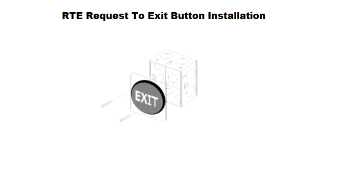
Request to Exit (RTE), Push Button Installation
The Request to exit button shall be installed on the secure side of the door.
Final location of the RTE shall be as per the approved Access control system layout drawing.
The Final mounting height of the RTE shall be as per the approved Access control System layout drawing.
Pullout the cable from the 3X3 back box installed embedded on the wall. Terminate the appropriate cable on the RTE and mount the RTE on the 3X3 back box.
All the labeling of devices and cables shall be in accordance with the approved Access control layout drawing.
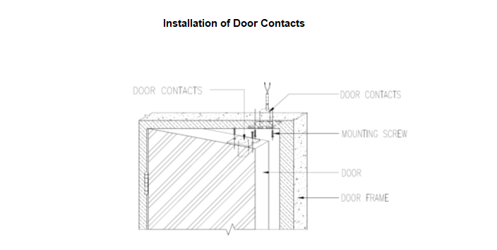
Installation of Door Contacts
Doors are monitored by door contact, MK-340-5W for timber and metal doors and FM106 for glass doors.
The cabled part for door contact will be installed on the door frame and the moving part of the door contact on the door shutter.
Final location and mounting distance from the door frame and door type will be as per the approved typical installation drawings.
All the labeling of devices and cables shall be accordance with the access control layout drawing.
Electromagnetic Lock, Drop Bolt, Contacts & Brackets
The final accessories set i.e. electromagnetic lock, drop bolt, door contacts, LZ bracket and U-bracket, their locations and mounting distance from the door frame and door type will be as per the approved door installation drawings.
Refer to set of drawings titled Wooden Door Detailed Drawing, Steel Door Detailed Drawing, Glass Door Detailed Drawings.
All the labeling of devices and cables shall be in accordance with the access control layout drawing.
Pre-commissioning of Access Control System
Pre-commissioning of Single Reader Interface / Dual Reader Interface
Pre Commissioning of single reader interface (ADS5200) & Dual reader interface (ADD5100) will be discussed in this section.
Ensure all installation works are complete as per approved method statement for installation of ACS system and drawings.
Ensure all the cables are tagged as per the design and connectivity’s are checked before proceeding to commissioning of the modules.
Ensure the power cables are properly connected before powering up the power supply of the modules.
Connect the laptop loaded with FLN software to the DRI or SRI RS 485 input with proper converter(RS232 to RS 485).
Download the firmware to the device and give appropriate address to the device.
Pre-commissioning of the SRI & DRI is complete.
Pre Commissioning of Input Point Modules
Ensure all installation works are complete as per approved method statement for installation of ACS system and drawings.
Make sure that all the cables are tagged as per the design, and connectivity is checked before proceeding to commissioning of the modules.
Ensure the power cables are properly connected before powering up the power supply of the modules.
Connect the laptop loaded with FLN software to the DRI or SRI RS 485 input with proper converter (RS232 to RS 485).
Download the firmware to the device and give appropriate address to the device.
Pre-commissioning of Input control module and output control module is done
Pre-commissioning of Advanced Central Controller
Ensure all installation works are complete as per approved method statement for installation of ACS system and drawings. Also ensure that ICT data network is ready and commissioned by IT contractor.
First Step involved in pre commissioning is to establish LAN network between ACC and commissioning laptop.
Connect ACC network port to the commissioning laptop Ethernet port with crossed cable.
Set the IP address of commissioning laptop to the range 192.168.1.xxx.
Establish a connection for the both with TELNET command.
Enter the Username with Password.
Now go to system settings and set password and date and time. For date and time define the IP address of respective communication gateway.
Go to network settings and change the IP address same as of your IT network plan.
Now change the IP address of commissioning laptop same as of your IT network plan.
Pre commissioning of ACC is complete.
Pre-commissioning of Card Readers
Make sure that the location and height of the installed card readers are as per approved security system shop drawing and typical installation details drawing.
Ensure all the cables are tagged as per the design and connectivity’s are checked before proceeding to commissioning of the modules.
Make sure that the card reader is properly terminated in the appropriate terminal before powering the card reader.
Ensure the card reader is connected to appropriate reader interface module in appropriate panel location as per approved schematic diagram/drawing.
Now power up the card readers and confirm all the card readers are working properly.
Check the LEDs are glowing properly and show any card to check the sound and reading distance of the card reader.
Pre-commissioning of Electromagnetic Door Lock
Ensure that the installation works of locks are completed as per approved security system shop drawing and typical installation details drawing.
Make sure that all the cables are tagged as per the design and connectivity is checked before proceeding to commissioning of the door locks.
Ensure the locks are terminated on the appropriate door Interface module.
Check that the +ve and –ve of the locks are terminated properly to avoid any power issues.
Ensure the doors are aligned and closing properly after the installation of magnetic locks.
Now Power-up the lock, then check and ensure the magnet is catching the armature properly.
Ensure the Monitoring/status LED of the lock turns red when the magnet is locked.
Pre-commissioning of Request to Exit and door contact
Kindly ensure all the devices are installed as per the approved layout and typical installation details.
Ensure all the cables are tagged as per the design and connectivity’s are checked before proceeding to commissioning of the modules.
Ensure all the cables are terminated on the appropriate terminals of the devices.
Pre-commissioning of Fusion (software installation procedure)
Surveillance Fusion is an Integrated Security Management System that brings together all aspects of security in one homogeneous system.
The systems / disciplines managed by the software include Access Control, Intrusion and Video Management Systems.
Fusion has a single integrated back end database for all these disciplines.
It provides an integrated User Interface for monitoring, managing and reporting across these multiple disciplines.
Fusion works on the Microsoft .NET framework.
It is essential to understand that the target machines are setup properly before the installation is started.
Fusion installation comprises of three steps.
Pre Installation Procedure
Installation Procedure
Post Installation Procedure
Pre Installation procedure is detailed in section 4.1 of the fusion installation guide which basically covers the operating system.
Installation procedure will further be divided into smaller components as follow.
Installation of Fusion Application Server Components
Installation of Fusion Data Base Server Components
Installation of Fusion Communication Gateway components
Installation of Fusion NVR Components
Installation of Fusion Desktop Client Components
Once installation works are complete post installation works starts.
For post installation activities we need to generate the user id and finally license registration. This is detailed in fusion installation guide.
Installation of Fusion Application Server Components
Fusion application server components will be installed on Server running operating system Windows Server.
Fusion application server components will be installed on 02 Nos. machines; one machine will act as Primary Application Server whereas the second machine will act as Secondary Application Server.
Follow the steps detailed in fusion installation guide for application server installation on primary and secondary machine.
Installation of Fusion Data Base Server Components
Fusion data base server components will be installed on Server running operating system Windows Server.
Fusion data base server components will be installed on 02 Nos. machines; one machine will act as Primary Data Base Server whereas the second machine will act as Secondary Data Base Server.
Follow the steps detailed in SQL Server installation guide for database server installation on primary and secondary machine.
Installation of Fusion Communication Gateway Components
Fusion Communication Gateway components will be installed machine running windows server operating system.
Fusion communication gateway components will be installed on 02 Nos. machines. Each machine running 6 Virtual enjoinments.
Follow the steps detailed in fusion installation guide for communication gateway installation.
Installation of Fusion NVR Components
Fusion NVR components will be installed machine running windows server operating system.
Fusion NVR components will be installed on all available machines. Each machine running 3 Virtual enjoinments.
Follow the steps detailed in fusion installation guide for NVR installation.
Installation of Fusion Desktop Client Components
Fusion desktop client components will be installed on the PC running windows operating system.
Fusion desktop client components will be installed on computers as per system requirements.
Follow the steps detailed in fusion installation guide for desktop installation.
Commissioning of Access Control System
Commissioning of Access Control Head-End Server
Install the Main server PC on the designated place as per the approved layout drawings
Connect the Main server to the nearest Data access point (DAP) provided by ICT department/contractor.
Install the Fusion surveillance software on the server and then install all the required licenses.
Now open the Fusion surveillance software on the server. Login through the Authorised username & password.
Ensure all the licenses are installed properly with required quantities.
Make sure that the data communication is established through the DAP and ping one of the Advanced central controller to confirm.
Now add all Advanced central controllers on Fusion surveillance software through the already assigned IP address.
Now give names/number to the Advanced central controller with respective floors & rooms. For example ACC installed at Level 0 Security Room then the ACC will be named as (ACC 1.)
After all the ACC’s are added with names then add all the Reader interface module and input point modules to the ACC’s with respective numbers.
After adding all the reader interface & input point modules, configure the doors and inputs connected to the modules.
While configuring the doors, field devices connected with corresponding doors will be also configured. For example door no D0028 is DRI-D0028-04 and it will be equipped with Card reader, magnetic lock, Door contact, break glass, Request to exit detector. Then configure all the field devices to the corresponding reader interface module.
Then configure the cards with card holder names and access level for the card holder.
Commissioning of the Access control system Head end server completed and the Testing procedures for the configured devices will be as below.
Main head end server of access control server will be placed in the designated area and it will not be used for day to day process.
The Client workstation with limited privileges will be provided for the daily usage on.
Testing Procedure for Card Readers
Swipe a valid card on the reader, it will give beep sound and Red LED changes to Green and the door will be unlocked.
Check the door status on the Fusion software.
Check the Alarm. It will display “ACCESS GRANTED” on the Fusion
Now swipe an Invalid card on the card reader. It will give continuous beep and LED remains on red.
Check the Alarm .It will display “INVALID ACCESS” on the Fusion.
Testing Procedure for Request to Exit Button
Press the Request to exit button. It will unlock the door.
Check the Alarm. It will display “VALID ACCESS” on the Fusion software.
Testing Procedure for Magnetic Contacts
Magnetic contacts are installed on the doors to identify the status of the door.
Swipe the card on the card reader and open the door.
Now check the alarm. it will display “ VALID ACCESS”. Then keep the door open for few minutes.
Now check the alarm. It will display “DOOR HELD OPEN”. Then close the door.
Now check the alarm it will display “DOOR HELD OPEN RESTORED”.
Commissioning of Fusion Application Server
Once the software installation is complete, assign IP address to the application server machine on OS level.
Application Server will be accessed by desktop client for rights.
Commissioning of Fusion Communication Gateway
Once the software installation is complete, assign IP address to the communication gateway server machine on OS level.
CG will be discovered automatically in the device browser windows of Fusion desktop client.
From fusion desktop client CG will be associated to field devices.
Commissioning of Fusion Network Video Recorder
Once the software installation is complete, assign the IP address to the NVR machine on OS level.
Commissioning of Fusion Data Base Engine
Once the software installation is complete, assign IP address to the database server machine on OS level. DB Server will be connected to Application server.
Data can be restored and archived from the DB server.
In order to open the DB achieve, Restore and backup utility from desktop client. Go to C:\Program files\Surveillance\fusion\Application Server\bin and open Euronet.DB.utility.exe.
Fusion DB utility will open. Follow the steps detailed in Fusion Data Base maintenance Guide to achieve, restore and backup DB.
Commissioning of Fusion Desktop Client
Desktop Clients or SMS Client Workstations are installed at Main Security Control Room.
Assign IP address to Desktop client on OS level.
List of Testing & Commissioning Checklists
Access Control System Testing Check List (General)
Access Control System Testing Check List (SRI/DRI)
Access Control System Testing Check List (IPM)
Access Control System Testing Check List (ACC)
Access Control System Testing Check List (Alarms)
Access Control System Testing Check List (Logs & Reports)
Access Control System Testing Check List (Badging Station)