Driven pile is selected for part of the foundation system. The specification of the driven pile system using Diesel Hammer is according to client requirements.
Positioning/setting out of the driven pile points will be performed using Total Station by a qualified surveyor.
The surveyor will also be responsible for accurate survey location during erection and prompt survey checking.
All pile points shall be measured based on existing Bench Marks approved by client.
Before measuring, first the existing bench marks will be checked for point accuracy and for this purpose existing bench marks (BM) from client shall be used as a reference.
After setting out each point is completed, the point shall be marked by appropriate marker.
All main setting out points shall be maintained safe and undisturbed.
Pile Lifting/Pitching and Handling
Pile pitching and handling shall be exercised with greatest care.
Lifting shall not be allowed outside tolerance of 10 cm from lifting position indicator.
All pile damaged during handling and lifting shall not be further used and must be replaced.
Pitching with procedure yet if damage still occurs, pile supplier must be contacted and he is responsible for replacement.
Piles may be suitably constrained to maintain their designed position by means of guides.
Piles deflected from the vertical or proper line shall, where appropriate, be withdrawn and re-pitched until the proper line is obtained.
Particular care shall be taken to prevent raking piles from sagging from their current position.
No forcible method of correction in the position or line of any pile shall be permitted.
Any pile damage during driving or which is driven out of its proper position or driven below the cut off level shall be corrected by either splicing the pile or by driving another pile or piles adjacent to the defective or low pile as appropriate.
Pile Verticality
Before driving process, it is compulsory to check the verticality of the pile using waterpass and/or survey equipment.
The pile shall be driven vertically and eccentricity shall be limited to maximum deviation of 75 mm.
Should piles be driven outside this tolerance the effect of the design and appearance of the structure shall be assessed and remedial measures shall be carried out by contractor.
Pile Lead and Cushion
Piles shall be supported in line and position with leads while being driven.
Pile driving leads shall be constructed so as to afford freedom of movement of the hammer, and shall be held firmly in position to ensure rigid lateral support to the pile during driving.
The head of all concrete piles shall be protected by caps of appropriate design having a suitable wood cushion inside.
Cushion shall be check and replaced regularly and have minimum thickness of 5 cm.
No pile head shall be held so firmly as to prevent the slight rotation of the pile normally occurring while the pile is being driven.
When the area of the head of any concrete pile is greater than that of the face of the hammer, a suitable cap shall be provided to distribute the blow of the hammer throughout the cross section of the pile and thus prevent, as far as possible the tendency to split or shatter the pile.
Pile Splicing/Jointing
Full length piles shall be used where practicable.
Where the use of splices is necessary the method of splicing shall follow Pile Supplier splicing drawing endorsed and approved by Client.
All splice shall be welded using full circumference butt weld type using AWS electrode minimum 3.2 mm executed by appropriate and qualified welders.
Inadequate splicing by contractor welders shall be rectified with regards to criteria set in approved splicing method.
Pile Driving Contingency
The pile driving process shall be executed continuously if possible to prevent built up skin friction in soil, driving process shall be stopped only during joint process and shall be
completed until final setting.
Piles must be driven and with length of pile shall be adequate to achieve the required working load capacity with a factor of safety of 2,05.
Pile Recording
Contractor shall maintain daily a complete record of all piles installed during the day.
The form of the records shall be prepared in a standard format.
The form shall include and not limited to:
1) Pile size, number of joint, total pile length used
2) Pile ID and position
3) Number of blows, hammer type, setting drop height
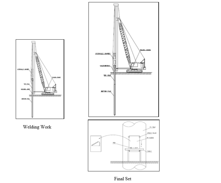
4) Settlement in 10 setting blows (Calendering)
5) Pile penetration from ground
6) Ground Elevation
7) Weather condition
Equipment and Hammer Selection
In order to gain good result in the driving process, careful selection of piling equipment and hammer type shall be implemented.
Piling crane of minimum 50 ton capacity shall be used to support the hammer DD85 & DD65 lifting and pile pitching and to suitably guide the pile into installation.
Hiley formula calculation for optimum drop height during calendaring recording process for various hammer types are listed in appendix.
Set criteria’s RC pile for hammer DD85 with a weight 8.5 ton and DD65 with a weight 6.5 ton.
Unexpected Ground Condition
Contractor shall refer immediately to the client any circumstances, which indicate that the ground conditions differ from those expected so as to effect materially the bearing capacity of
the pile.
Whenever hard lense is detected during the soil investigation process, main contractor/owner shall take precautionary method by pre drilling process or take account design to be based on lense
area, this is due to fact that HSPD will most likely to set at SPT>=50 and unable to penetrate hard lense in certain thickness and depth.
Jacking Using Dolly
For cut off level of pile below ground level, contractor shall use dolly/another section of pile to push in the used pile to the appropriate top pile design (1 m higher from C.O.L of pile).
Suppose any used pile is jacked lower than 1 m top pile, it has to be more than 40D high from C.O.L. otherwise to extend and splice more pile segments, or to extend rebar up to 40D.
Pile Installation Requirements
Minimum concrete age is 14 days and the concrete compressive strength reaches 80% of the compressive strength of the plan.
Use a plywood / multiplex dry pile cushion on the Hammer cap to prevent damage to the pile head.
Replace the pile cushion if it is not elastic (highly compression), it has been charred or burned when erecting the pile.
Enforcement of the pile by binding the lift sling to the marking position for enforcement on the pile.
Fixing point according to the layout of the foundation point and the length of the pile segment is enough to reach the depth of the plan.
The position of the pile and pile leader is parallel.
Co-centric pile axis (one line) against the impact hammer axis.
The pile is connected by full welding on the connecting plate grooving / gap.
The connection pile erection is continued after the welding work and inspection completed.
Condition of the cocentric connection pile to the pile that will be connected.
After connecting, for the location of non-corrosive plates and allow for the corrosive location coated with free tar epoxy.
The minimum pile set value is 25mm / 10 blows to avoid damage to the pile on the head / under the pile.
The estimated capacity for the final set criteria shall be as per approval.
Prepare pc pile and prime paint material (cat meni).
Mark the pc pile with paint with distance each 1 m big size and 0.5 m for small size.
Marking of pile it is mean to indicate of pile penetration.
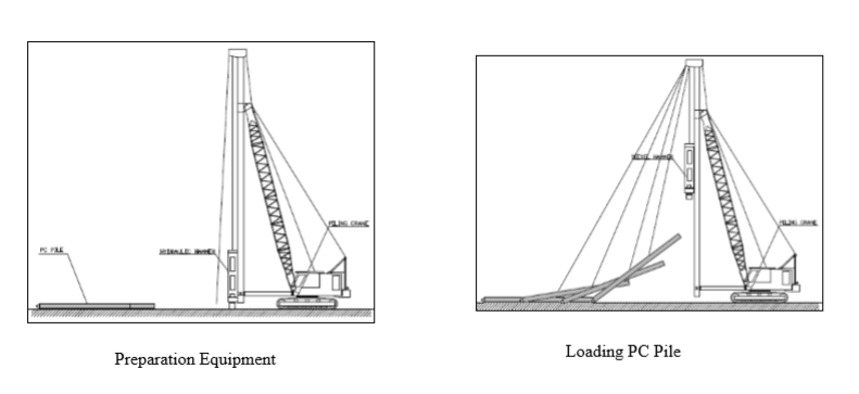
Prepare all of equipment including piling rig, hammer and PC Pile material.
Ensure that lifting sling in good condition.
Ensure that PC Pile material in good condition and no defect or crack.
Ensure that pile cushion (15cm) already installed.
Tie the PC Pile using lifting sling.
Ensure that PC pile has been tied in double condition.
Ensure that no body is present or allowed in surroundings of lifting area.
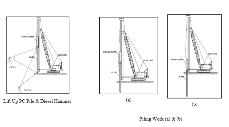
Then lift up the PC Pile and hammer using piling crane carefully.
Then insert the pile head into the hammer cap.
Lift up PC Pile and Diesel hammer together.
Then put the tip of pile on the point position.
Check verticality from two perpendicular direction using plumb-bobs or theodolites.
Re check that all condition is ok.
The first hammer will be set in low jump.
Then start the driving work using hydraulic hammer.
Continue the pile driving work until remaining 60 cm from ground, then prepare for welding work.
Pile Welding Work
Prepare top pile, welding machine and welding electrode.
Lift up the top pile using crane.
Put top pile on the bottom pile.
Check straightening of both piles.
Then start welding work as per approved welding procedure.
After welding work completed then check by visual test procedure.
Then check by NDT / Penetrant 10% of total joint.
Finally result of welding will be touch up coated using free tar coat material.
Then continue the driving work.
Take final set or calendaring and check or calculate the bearing capacity of pile by dynamic formula.
If the capacity of pile has reach design capacity then the driving work can be terminated.
If the capacity of pile didn’t reach design capacity yet continue to driving work until top of pile reach ground level.
Then the piling work can be terminated.