
Below is a precise method statement for fire hose reel testing and commissioning part of project fire fighting system.
Automatic wet system is a system that is attached to a water supply capable of supplying the system demand at all fires and that requires no action other than opening a hose valve to provide water at hose connection.
Prior to performing the functional test of the fire hose reel system the following shall be checked/verified:
- Approved make and recommended materials by the manufacturer / supplier are used at site.
- Check that the Hose Reel Cabinets, Landing Valves and its accessories are installed as per the approved drawings for its quantity and location.
- Ensure that the Fire Extinguishers are installed as per the approved drawings for its quantity, type and location.
- Make sure that all drawings are approved by the civil defense authority.
- Check that all the fire extinguishers are in proper condition for its pressure, Tag and mechanical seals.
- Make sure that painting of the piping system is done and approved.
- Check all the valves, pipes and bolts are tightened properly.
- Hydraulic testing of the piping system is already done in accordance with NFPA and the approved method of statement. If not tested follow below steps.
- Ensure that the supervisory control valve for the fire hose cabinet is installed & electrically connected to fire alarm system.
- Ensure that all valves are properly tagged & identified.
Hydrostatic Testing of Fire Hose Reel System
Plug all the openings.
Close all the drain valves.
Fill complete pipeline with water avoiding any air column, for this purpose keep the drain valve at the highest elevation slightly open, while filling water when line is completely filled with water close the valve.
By using a pressure pump pressurize the line to an intermediate pressure, say 100 psi. Wait for 5 minutes; check all major joints for any visible leak.
If the firefighting piping system is not showing any leakage, again pressurize the system to 150 psi and wait for 10 minutes for any drop in pressure or leakage.
Still if the system is found leak proof pressurize the line up to 200 psi and keep the pressure for at least 2 hours.
Minimum pressure requirements:
Hydraulically designed to provide 10 GPM (37.85 lpm) at a minimum residual pressure of 2.2 bars at the outlet of the hydraulically most remote 1” dia. Hose reel connection.
Hydraulically designed to provide 100 GPM (378.5 lpm) at a minimum residual pressure of 4.5 bars at the outlet of the hydraulic most remote 1 1/2” dia. Fire hose connection.
Flushing after Pressure Testing
Prior to perform the final testing and commissioning of the internal fire hose reel and Fire Hose system flushing shall be conducted as follows:
Pull the hose reel or fire hose outside the building or inside the toilet area
Direct the hose to a free direction.
Open the valve.
Keeps water going for 2-3 minutes?
Continue the flushing till all debris are removed and clean water is coming out.
Close the valve.
Repeat the same procedure for all other systems.
Fire Hose Reel Testing and Commissioning Method
Equipment/Instruments to be used
- Adjustable Spanner.
- Pressure Gauges.
- Pipe Wrench.
The following are to be checked prior to handover of the Fire Hose / Hose reel System to the Clients/ End Users.
All Fire Hose System Network and attached appurtenances subjected to system working pressure shall be hydrostatically tested at 200 psi. (13.8 bars) and shall maintain that pressure without loss for 2 hours.
Pressure loss shall be determined by a drop in gauge pressure.
The piping system shall be flush tested to ensure thorough cleaning of the network piping.
The minimum flow rate shall be at least that necessary to provide a velocity of 3 m/ sec.
Ensure all the components of the fire cabinets are installed properly (landing valves, hose reels, extinguishers & fire hoses).
Check pressure in all the floors by using special adapter with calibrated pressure gauge and note the readings.
Open the lock shield valve of each hose reel and adjust its pressure to 3 – 4 bars through 1″ PRV.
The water throw should be 6 meter, hose reel should be opened inside toilets or outside the building to avoid any damages to other services.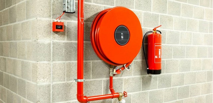
Check all the fire extinguishers for its certification (inside pressure & hose connections also to be checked).
A system functional test may be conducted as given below once the entire fire protection system is completed.
Ensure that all the pre-commissioning checks are carried out successfully.
Open the supervisory isolation valve for the fire hose cabinet & allow the water to flow into landing valve & hose reel.
Hose Reel
Pull out the hose from the hose reel to a length of approximately 3 meters & ensure that the automatic valve opens & the fire alarm signal is generated.
Ensure that the complete length of hose will open in all directions only by pulling the nozzle without even touching the hose reel.
Adjust the nozzle to set the required throw / flow of water.
Check for any leakage in the hose reel connections.
Check the pressure in the PRV down stream which should be 65 psi.
Hose Rack
Pull the hose from the hose rack.
Open the landing valve & check the water flow from the nozzle.
Check if the fire alarm signal is generated.
Check for any leakage in the hose connection / pipe joints.