
This Method Statement covers the HVAC dampers and Accessories horizontal and vertical installations. The procedure defines the method used to ensure dampers and accessories installation has been carried out as per standards, contract requirements, and best practices.
Method statement gives details of how the ductwork will be carried out and what health and safety issues and controls are implemented for safe system of work.
References & Standards
- Contract Specifications
- Approved shop drawings
- SMACNA- HVAC Duct Construction Standard.
- Inspection and Test Plan.
- Project Safety Plan.
- Project Quality Plan.
- Project Logistics Plan.
- Relevant QMS Procedures
- JSEA Job Safety & Environmental Analysis
- Related International standards ( ASME , ASTM -A653A , 653M and ASHRAE standard)
Necessary Tools & Equipment
Arrange below listed minimum tools and equipment that must be in good condition and maintained.
- Riveter
- Sheet Metal Shear (straight, left and right)
- Shearing Tools
- Hammer
- Electric Drill
- Screw Driver
- Punching Tools
- Mallet
- Grinder
- Adjustable Wrench
- Sealant Gun
- Monkey Wrench
- Vice
- Grip
- Vice clamp
- Steel Square
- Plumb Bob
- Spanner set
- Duct Stretcher
- Spirit level
- Philip screw
- Accordion type riveter
- Measuring tape
Roles & Responsibilities
Project manager shall be responsible overall to complete all MEP works as per specifications, budget, time, & project quality and safety plan.
MEP Site Engineers shall be responsible for but not limited to the following important activities:
Ensure that all the preparation and application works are carried out according to the contract specification and manufacturer’s data sheet(s).
Make sure that the progressing of works is carried out according to the planned program, and as per the approved Method statement.
To ensure that all the equipment’s and materials required in executing the works are available according to the planned construction program.
Coordinate with the main contractor’s MEP coordinator and safety officer for all safe and proper execution of the work in accordance with the risk assessment.
To coordinate with the civil team for any area preparation, access, clearance.
Foreman shall be responsible for but not limited to the following important activities:
Guide and control the tradesmen and charge-hand(s).
To ensure that work is done as per the approved shop drawing(s).
Report all activities, requirements and issues to the MEP site engineer.
Health and Safety Officer shall be responsible for but not limited to the following important activities:
a. Ensure health and safety of the site personnel.
b. Ensuring PPE available with site personnel
c. Good housekeeping on site
d. Environmental concerns are addressed.
e. Responsible for implementation and assurance of the safety and environmental requirements (JSEA).
QA/QC Quality control engineers shall be responsible for but not limited to the following important activities:
Raising MIR for consultant approval.
Inspecting the materials on site as per approved materials submittal prior to installation on site.
Inspection for the installation as per approved drawings and approved test plans and checklists.
Preparing test forms for testing on site and updating results accomplished.
Issuing inspection request within 24 hours before the actual inspection.
Responsible for the assurance of Quality control, method statement and inspection test plan.
Controlling the shop drawings flow on project site.
Material Delivery, Handling and Storage
Dampers and Accessories material and its associated material supplied will be packed for protection against damage during handling, transport, storage and installation.
The material to be delivered in self supporting framed units.
Dampers and Accessories material will be stacked as loose with all material parallel (nested).
Material will be stored in clean and closed store on raised floor for protection and according to manufacturer’s recommendation.
Dampers and Accessories material will be stored in closed shaded area and should be stacked properly, and covered with PVC sheets.
Inspection of Materials in Store
Notify MEP Engineer and consultant upon delivery of fire damper material at site.
All materials shall comply with the approved Material Submittal.
Upon the receipt of materials on site, these shall be inspected by the QC Engineer / Inspector to ensure correctness of material as the Approved Material Submittals and quantities, prior commencing works.
Ensure that the materials are handled properly, and protected against dust, dirt and foreign matter.
A material inspection report shall be prepared by QA/QC Engineer I Inspector for submission to the Consultant for review and acceptance.
Material not complying with the Material Submittal or unusable/damaged duct or fittings will be placed in a quarantined area and clearly labelled.
Check that identification stickers have been given for each piece.
Make sure that the fusible links work properly.
Sequence of Work for Dampers and Duct Accessories Installation
The works shall be executed in accordance with the following methodology and sequence;
Pre-installation checks
A pre-start meeting prior to the commencement of the works will take place with the Site Engineer, H&S Officer, QC Engineer, and Supervisor/Foreman in charge to address the following:
Material is approved by the consultant.
Notification to start the work to be issued (where as applicable).
Area has been surveyed and ready for installation as per approved drawings, installation area is clean from debris and foreign matter, area is safe to carry out the work.
Ensure that adequate number of tradesmen and proper tools are available.
Latest approved shop drawing for this installation is present, and all personnel are working off the same drawing.
Area for materials preparation / fabrication workshop for ducting installation has been identified and procedures are in place.
Emergency wash area is available near the fabrication areas, in case of workers skin contamination with resin or other chemicals.
Temporary DBs are provided and inspected regularly by the electrician prior to execution of the works.
Ensure that the related mock-up is accepted /approved by the consultant.
Installation Method of Dampers and Accessories
Mark from approved drawings the position of all dampers and accessories on slab or section as is possible by the program/ related progress on site.
Dampers and Accessories supports, hangers, spacing shall be as per SMACNA standard and approved shop drawings and material submittal.
For full details regarding hangers and supports requirements refer to the “Hangers & Supports” method statement.
Checking of Dampers and Accessories prior assembly
Check that all the dampers and accessories are tagged and that the correctly tagged sections are available for the job/area.
Make sure that the dimensions are correct. Where dimensions are shown on the drawing these are internal dimensions.
Dimensional tolerances are ±2 mm
Check that the Dampers and Accessories are free from any defects or holes.
Make sure that the Dampers and Accessories are clean.
Installation Steps
Handle dampers by frame. Do not lift by blades, linkages, actuators, or jackshafts.
Use sufficient people to evenly lift multiple sections assemblies.
Do not drop, drag, step on.
Do not apply excessive bending, twisting or racking.
Cycle dampers by hand before installation in the duct; to insure freedom of movement.
Inspect duct work or opening where damper will be installed for any obstructions and to ensure it is straight and level.
It is essential to support duct work before and after the damper to prevent sagging due to damper weight.
Determine the location of the extended drive shaft (handle) before installation to ensure accessibility and good coordination.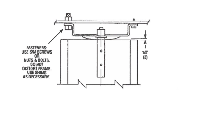
For multi-layers damper; position the damper sections together in duct or opening, and ensure to align and match the frame markings on adjacent sections.
Align holes on adjacent frame sections and fasten together on front and back side with screws or nuts and bolts of appropriate sizes.
Use shims as appropriate between damper frame and exhaust duct opening and between damper sections as necessary to prevent distortion of fame by fastening.
Make sure the fasting do not interfere with blade movement or damper linkage.
After installation of low leakage dampers with seal, caulk between frame and duct opening to prevent leakage.
Maintain the side at which the handle is being kept.
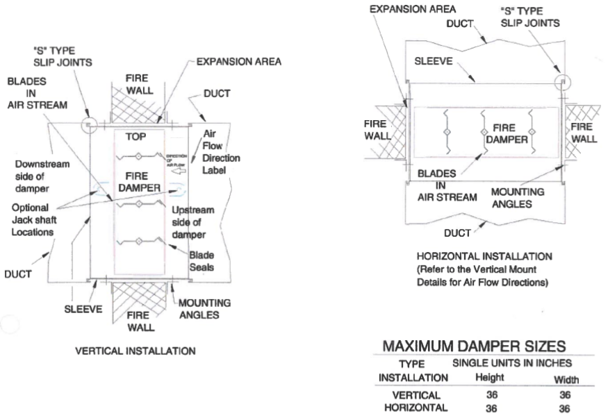
Fire Damper Installation
Make sure that each fire damper is marked with 1-1/2 hours UL 555 Classified fire damper label.
The fire damper meets all UL and NFPA criteria for primary fire dumpers in walls and floors with fire resistance ratings of less than 3 hours.
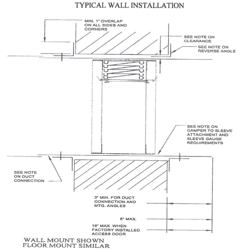
The basic intent of proper installation is to secure the fire damper in, not to, the opening in such a manner as to prevent distortion and disruption of the damper operation by allowing the fire damper in openings to expand and the connecting duct to separate in the event of the collapse of the hanging system. The fire damper must be positioned with in the masonry block or gypsum wallboard fire barrier.
The opening in the wall or floor for the fire damper shall be sized so as to provide expansion clearance between the sleeve and opening . Clearances do not vary with walls constructed of different materials. A minimum of 1/8″ per foot of overall damper/sleeve width and height is required. The maximum opening size shall not exceed 1/8″ per foot plus 1″, minimum total clearance shall be at least 1/4″ larger than the overall assembly.
Not to rest the fire damper on walls.
Independently supported break away connection to be given before/after the fire damper.
Direction of flow to be maintained as per the tag inside.
Access doors & all related accessories to be provided as per the details.
Suitable access must be provided for damper inspection and servicing. Where it is not possible to achieve sufficient size access, it will be necessary to install a removable section of duct.
Identification sticker indicating fire dampers to be fixed before the damper in accessible area.
Caulking is allowed between the mounting angles and the damper sleeves and between the mounting angles and the floor or wall construction.
Caulking is not allowed between the damper sleeve and the wall or floor inside the opening.
Caulk shall be one of the following:
Dow Coming RTV 732, or a UL approved substitute as per project approvals.
Duct Connection of Fire Dampers
The installation of the damper and all duct connections to the damper sleeve shall conform to NFPA-90A and the SMACNA Fire, Smoke and Radiation Damper Installation Guide.
All duct connections shall also conform to UL555.
Connecting ducts shall not be continuous but shall terminate at the damper sleeve.
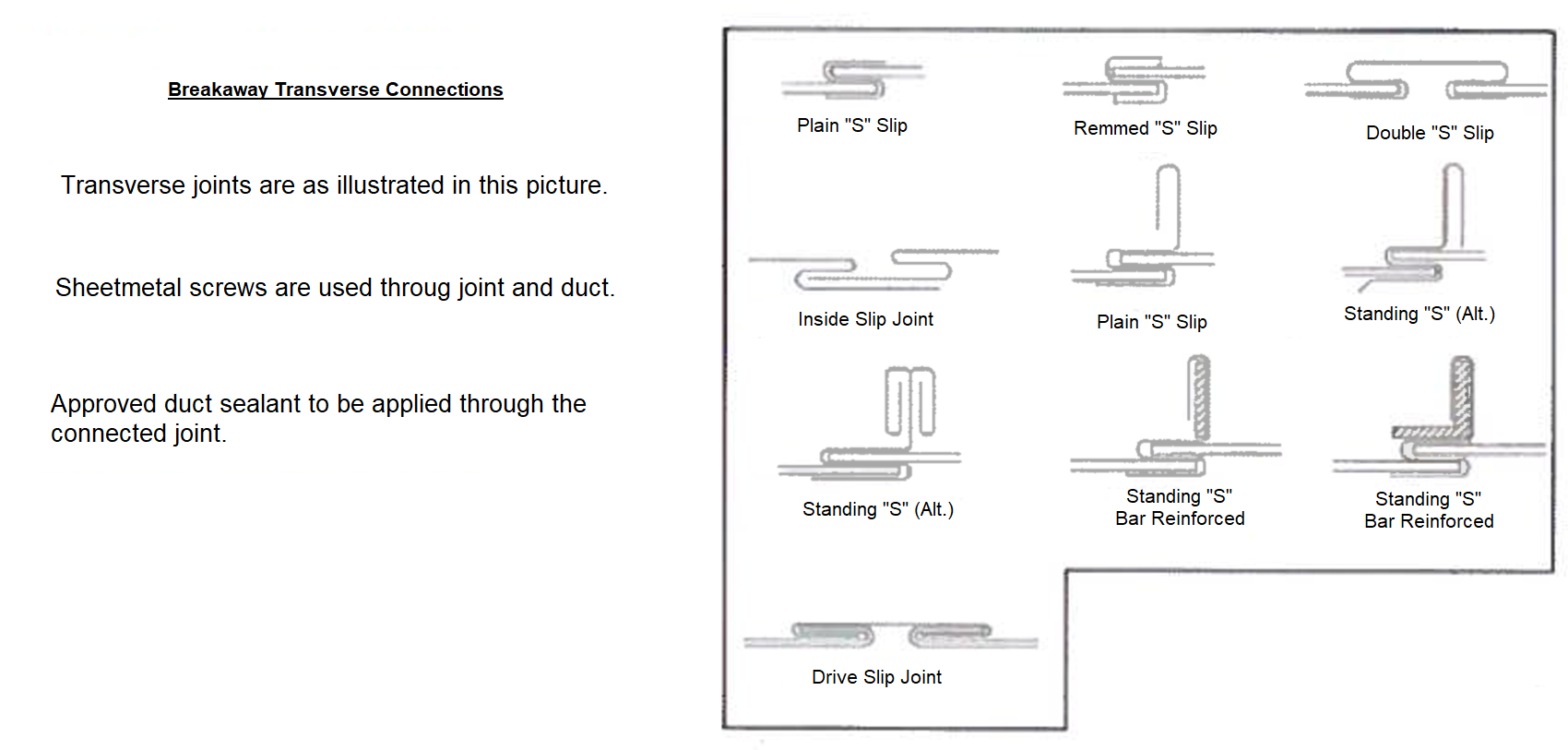
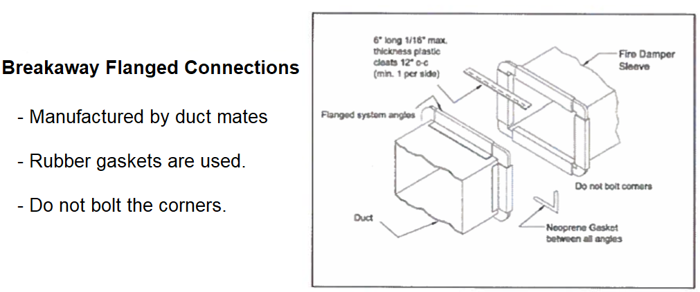
Duct connections to the sleeve will be either of the breakaway or rigid types, breakaway types are listed below.
The following determines if the connections are to be rigid or breakaway.
For rigid type duct connections, sleeve shall be a minimum of 16 GA on dampers not exceeding 36″ wide or 24″ high or 24″ diameter and 14 ga on larger units.
Dampers supplied with thinner sleeves will require a breakaway connection of the following type. Plain “S” slip, double “S” slip shown below. Slip to be in accordance with size of duct, can be with standing ‘S’ type too for ducts with larger widths.
All connections not listed as rigid shall be considered as breakaway.
Breakaway joints of the types shown below shall have no more than two No.10 (4.8 mm) diameter sheet metal screws on each side and on the top and bottom located in the center of the slip pocket and shall penetrate both sides of the slip pocket.
Breakaway joints of the type shown below are permitted on the top and bottom of horizontal ducts (vertical dampers) with flat slips not exceeding 20 inches (508 mm) in length on the sides.
Mounting Angles
Secure mounting angles to the sleeve and not to the wall or floor.
Mounting angles to frame the four sides of the sleeve on both faces.
When reverse mounting angles are used the size of the opening must be increased to maintain the specified expansion clearance between the angle / fasteners and the opening.
Angles shall be a minimum of 1-1/2″ x 1-1/2″ x 16 ga on dampers 36 x 50 and smaller.
For dampers greater than 36 x 50, angles to be a minimum of l-1/2 x l-1/2 x 14 ga.
Fasten angles to the sleeve using l/4″ dia. bolts and nuts or by welding with beads 1/2″ in length, or with No. 10 steel sheet metal screws, or with 3/16″ steel rivets.
Fasteners or weld beads shall be 8″ maximum on centers.
Fire Damper Maintenance
Dampers shall be maintained in intervals as stated in NFPA-90A, Appendix B, unless local codes require more frequent inspections.
Check the fuse link, check the stainless steel closure springs where furnished, cycle damper and check for free operation and complete closure, clean with mild detergent or solvent, secure damper open with fusible link.
Dampers Installation General Instructions
Damper shall be fastened to sleeve. Mounting angle shall be a minimum of 4 cm x 4 cm x 2 mm thick and fastened to the sleeve and damper only on all 4 sides with 6 mm bolts.
Angle shall not be fastened to each other at the corners or fastened to the fire wall. Angle may be reversed when diffusers or grilles require flush mountings.
Installation per NFPA 90A, UL555, and SMACNA fire smoke and radiation installation guide.
Fasteners must be placed where they do not interfere with the damper operation.
Sleeves shall be of the same gauge or heavier than the duct to which it is attached Gauge shall conform to SMACNA or ASHRAE standards.
When the following sleeve connections are used, the minimum gauge of the sleeve shall be 16 gauge on dampers not exceeding 36″ W x 24″ H and 14 gauge on larger dampers.
a. Angle reinforced standing seam.
b. Angle reinforced pocket lock.
c. Companion angles.
d. Metal fasteners approximately 16″ on centers.
The following breakaway sleeve connections may be used on all systems:
a. Plain “S” slip
b. Hemmed “S” slip
c. Bar slip
d. Standing “S” slip
e. Reinforced bar slip
f. Angle slip
g. Inside slip joint
h. Double “S” slip
Clearance for expansion of 1/8″ per foot of sleeve dimension is required. Angles should lap masonry a minimum of 1″ around the entire opening.
Maximum sleeve extension is 6″ on both sides of wall or floor opening for dampers without actuators.
Maximum sleeve extension is 16″ on both sides of wall or floor opening for dampers with actuators.
Dampers may be installed in wall or partition (masonry or gypsum wallboard) or concrete floor, but never supported directly on the wall.
The connecting ducts shall not be continuous, but shall terminate at the sleeve or frame.
Dampers are supplied with factory mounted actuators designed to close automatically upon detecting heat or the loss of actuator power.
Installation requires the “AIR FLOW DIRECTION ARROW”.
A continuous bead of Dow Corning RTV-732, Dow Corning 999 or GE-1200 silicone rubber sealant shall be applied between the damper and the sleeve for its entire profile on one side of the installation as a minimum.
Installed damper units require operational checks upon completion to ensure proper functioning.
An access door is a NFPA requirement for damper inspection and testing and maintenance, power and control cables shall be provided accordingly.
Inspection Checklist for Dampers Installation
Check that relevant MIR & Shop drawing are approved.
Support are properly fixed and level as per approved drawings.
Check if the dampers are free from visible damages
Dampers are leveled and supports are properly installed
Check the connection of the duct and duct accessories are properly clip or sealed.
Nameplate/identification tags of the units are provided as per the material submittal.
Check the access door panels, sizes and location and accessibility of damper’s and fusible links.
Verify that the damper installation is as per manufacturer’s instructions.