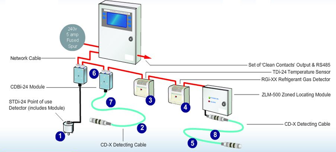
The purpose of this procedure is to define the step by step method to implement the correct practices for the pre-commissioning & commissioning of Leak Detection System through the guidelines contained herein.
Ensure that the job execution complies with the project requirements and serves the intended function to satisfactory level.
Tools & Equipment Required:
- Portable Hand tools
- Step Ladder
- Insulation Resistance Tester
- Continuity tester
Pre-Commissioning Procedure for Leak Detection System
Ensure that the Leak Detection system installation is complete and mechanical completion is approved.
Ensure that no damage has occurred between mechanical completion & precommissioning.
Check for proper installation of leak detection panel & the wiring termination to the leak detection panel.
Check the leak detection cable is properly installed & there are no open ends.
Make sure the surface that the cable is laid is completely clean, dry & free from dirt, oil or any conductive material likely to come in contact with the sensing cable.
Make sure that the accurate room map which shows the location of cable as well as key points which are potential sources of leaks is readily available.
Check the availability of power to the leak detection panel.
Repair / replace damaged components, if any.

Commissioning Procedure for Leak Detection System
Ensure that all the pre commissioning checks are carried out successfully.
Set the DIP switches SW2-1 to SW2-4 for address-1 (all off)
Set the DIP switch SW2-5 for 9600 baud.
Set the DIP switch SW2-6 for desired display units either feet or meters.
Set the DIP switch SW2-7 for latching or non-latching leak readings.
Set the DIP switch SW2-8 for non-map mode (twenty seconds delay for leak alarms)
Set the DIP switch SW3-1 to SW3-3 for the 4-20 mA range.
Set the DIP switch SW3-4 for the leak detect alarm relay to be supervised or non-supervised.
Set the DIP switch SW3-5 for the cable fault alarm relay to be supervised or non-supervised.
Set the DIP switch SW3-6 for the alarm relays to be reset from the display silence switch.
Set pot RA1 (sensitivity) for desired trip point.
Turn ON the power to the unit & observe the following:
(a) LED DS9 (power) is ON.
(b) LED DS8 (active) is flashing at 0.5 second rate.
(c) LEDs DS6 & DS7 are flashing at 0.5 second rate.
(d) The NORMAL LED is green.
Press the silence key to view the leakage current on the cable. A clean cable will indicate zero.
Press the switch again to view the measured cable length.
Test the cable for leak detection using a moist cloth on the cable at several points.
Check the leak detected LED glows & the signal is conveyed to the BMS.
Check the Leak detected LED switches OFF when the signal is acknowledged in the panel.
Attachments
- Pre Commissioning check sheet for Leak Detection System
- Commissioning check sheet for Leak Detection System
- Risk Assessment
Discover more from
Subscribe to get the latest posts sent to your email.
