
1. PURPOSE
The purpose of generating this Method Statement is to define the procedure step by step to implement the correct practices for Installation of LV Switchboards, MCC’s, Capacitor Banks, Variable Frequency Drive’s, SMDB’s & DB’s contained herein so as to ensure that the job execution complies with the requirements and serves the intended function to satisfactory level.
2. SCOPE
This Method Statement refers to various work procedures contained within project control documents, which explains and covers the Installation of LV Switchboards, MCC’s, Capacitor banks, VFD’s, SMDB’s & DB’s.
3. RESPONSIBILITIES
Engineer In-charge (Electrical) / Site Engineer (Electrical)
4. TOOLS / EQUIPMENTS
4.1. Fork Lift or Crane with capacity & arrangement in line with the Manufacturer’s recommendations, pallat mover and as required at site.
4.2. Portable hand tools.
4.3. Portable Drilling Machine/ Grinding Machine & Angle Cutter.
4.4. Spirit Level
4.5. Level Threads
4.6. Hydraulic Crimping tool
4.7. 500 / 1000 volt Insulation Tester
4.8. Digital multimeter
5. MATERIALS
LV Switchboards, MCC’s, Capacitor Banks, VFD’s, SMDB’s & DB’s and accessories shall be in line with the approved material submittal and approved drawing by local authority as per rules and standard.
6. HANDLING & STORAGE
On receipt of the LV Switchboards, MCC’s, Capacitor Banks, VFD’s, SMDB’s & DB’s and accessories at site, necessary precautions shall be taken for unloading, shifting & storage, as follows:-
6.1. Material shall be stored in a covered / dry space at all the time.
6.2. All materials received at site shall be inspected and ensured that the materials are as per approved material submittal.
6.3. Any discrepancies, damage etc., found will be notified and reported for further action.
6.4. suitably and in case if the repairs could not be done properly, the panel boards are to be sent to assembler for rectification, after all formalities carried on.
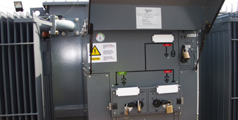
7. INSTALLATION GENERAL REQUIREMENTS
7.01 Ensure that the work area is ready and safe to start the installation of LV Switchboards, MCC’s, Capacitor Banks, VFD’s, SMDB’s & DB’s.
7.02 Ensure the installation of LV Switchboards, MCC’s, Capacitor Banks, VFD’s, SMDB’s & DB’s are carried out in accordance with manufacturer’s installation recommendations, requirement of applicable standards and in accordance with recognized industrial practices and specified in project specification to ensure that installation complies with requirements.
7.03 Prior to start the installation, refer to the approved shop drawings related to the area of installation and ensure that required materials are available at site as per approved material submittals.
7.04 Ensure the materials are stored properly and there is no mark of damage or deformity of any kind before issuing the material from site store. All materials and accessories should also be free of dust, scale, or oil.
7.05 Ensure that the issued materials are of approved specifications / submittals and as per the the requirement of the area shop drawing’s. (i.e. Make, size, Model / Type etc.,).
INSTALLATION PROCEDURE FOR LV SWITCH GEARS, CAPACITOR BANKS, MCC, VFD
7.06 Installation works shall be carried out only with respect to approved shop drawings of latest revision.
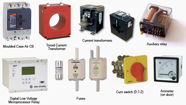
7.07 All components of the Panel Boards, MCC, VFD such as relays, fuses, CT’s, contactors meters etc., shall be verified against the approved material submittal.
7.08 Ensure all civil and finishing works are completed for the area of installation and released/ cleared by civil section to proceed on for further work of shifting, positioning of Panel Board / MCC/VFD installations. Also ensure that the work area is clean and safe to take up activities.
7.09 Ensure the floor surface is ready with base frames grouted to install the switch gear.
7.10 Minimum clearance of 750 mm (as per regulation) shall be maintained at rear side of the panel so that easy access for termination of cables and other maintenance works can be carried out.
7.11 Switchboards shall be installed serially and with Level Verticality in accordance with the Manufacturer’s recommendations, approved site layout and as per site requirement.
7.12 Check cabinet interconnections, bus bar connections, control wire connections between the cubicles after proper alignment of the sections cubical as per manufacturer’s drawing and approved shop drawing.
7.13 All knockouts made on the panel covers shall be filed and provided with grommets to avoid sharp edges and unused knockouts shall be covered.
7.14 Connection of Bus bar Trunking with all panel boards shall be done rigidly with proper supports.
7.15 Cables bending radius should not be less than the 8 times of the Cable diameter in line with the Manufacturer’s recommendation.
7.16 Appropriate tools & tackles such as Rollers, Pull Cords etc., to be utilized, while cable pulling operations including Pulling winch for longer lengths.
7.17 Termination of Cables shall be done using approved cable glands and lugs. Glanding and connections should be done only by competent technicians / electricians.
7.18 All panel boards and switch gears shall be provided with proper earthing connections as per approved shop drawings.
7.19 Complete wiring & terminations related to BMS shall be as per approved shop drawings.
7.20 Manufacturer recommendations are to be followed for all relay, timer and other breaker current settings, as per the total connected loads and the discrimination study of the system.
7.21 Identification labels of approved type shall be fixed on all panel boards.
7.22 Co-ordinate with the Main Contractor and ensure provision of Chequer plates on the open trenches inside the LV Room & Electrical rooms.
7.23 Ensure that all Cable entries and other openings of Electrical / LV Room, Wall / Floor are sealed with proper approved sealant.
7.24 Manufacture representative to verify the Site installations and provide acceptance of same prior to Energisation of Panel boards after obtaining clearance from Site Engineer
INSTALLATION PROCEDURE FOR SMDB, DB
7.25 Installation works shall be carried out only in Accordance to approved shop drawings of latest revision.
7.26 Ensure all civil & finishing works are completed and area is released for the area of installation and cleared by civil section to proceed on with Distribution board installations. Also ensure that the work area is clean and safe to take up activities.
7.27 Ensure the floor/ wall surface is ready to install the Distribution Boards.
7.28 Clearances are to be maintained between the SMDB’s and between the DB’s, as specified in the approved shop drawings.
7.29 Height of the Distribution Boards shall be maintained as per approved shop drawings so that easy access for termination of cables and other maintenance works can be carried out.
7.30 Connection of cable trays with all Distribution Boards shall be done rigidly with proper supports.
7.31 All knockouts made on the panel covers shall be filed and provided with grommets to avoid sharp edges and unused knockouts shall be covered. All cable entries shall be closed and sealed in a proper way.
7.32 Termination of cables shall be done using approved cable glands and lugs Glanding and connections should be done by only competent technicians electricians as per the approved
shop drawing.
7.33 All SMDB’s, DB’s shall be provided with proper earthing connections as per approved shop drawings.
7.34 Doors of all SMDB’s, DB’s are to be earthed with flexible connection.
7.35 Identification labels of approved type shall be fixed on all SMDB’s, DB’s.
8. INSPECTION
Inspection I : Installation of LV Switch Boards, MCC’s, Capacitor Bank, VFD’s, SMDB’s & DB’s
9. ATTACHMENTS
9.01 Risk Assessment
9.02 Inspection And Test Plan
9.03 Quality Control Procedure
9.04 Check Sheet