
This Method Statement provides the control sequence of construction and methodology that will be used for the supply, installation and maintenance of dewatering system over the entire project at any stage based on the following data:
Required Data:
Water Table level : m
Depth of excavation : -2.30m (Gen)
Depth of excavation : -3.30m / 5.50m (Max)
Shoring : Open excavation
Equipment Required:
- 6”, 8” discharge collectors.
- Dewatering pump, 150mm SD fully automatic, positive priming diesel engine drive pump.
- 6” diameter GI/PVC header pipes with quick action couplings leading the suction line to the pump.
- Well point riser assembly will be UPVC units, shatter proof, with 1M long slotted filter screen, 2”dia.
- Riser assembly will be coupled to the suction header line with armored flexible swings.
- Jetting Pump.
- Sedimentation tank/Settlement tank.
- Capacity of Pump 320 m3/hrs.
Well Point System Dewatering
Excavation shall be done up to a level of 50 cms above from the water table level all around the required areas as noted in the scope of work.
Contractor shall install well point dewatering system at this reduced level, as shown in the drawing.
A high pressure-jetting pump with jetting tube and hoses shall be used to create voids in the soil.
Pre-auguring shall be carried out if the soil is found to be hard.
50mm dia PVC well points with 1.00m screen shall be placed within the jetted hole at an interval varying from 1.5m-2.0m and 10mm.
Aggregates, if required, will be filled around the annular space to act as a filter medium.
Well points shall be connected to the headers through flex-bows and headers in turn to the self-priming centrifugal pump placed at a reduced ground level.
Pumps will be started and dewatering will be done continuously.
Excavation can be continued to achieve the required level.
Hand excavation shall be carried out near the well points and headers to ensure that there is no damage to these components.
In the event of any over bleed or uncontrolled seepages, the same water to be canalized to allow for sumping out of the water.
Trenches for the same purpose have to be arranged / provided by the Contractor.
Abandoned Dewatering System
Once the excavation reaches the final invert level, the dewatering system, if required to facilitate the construction, will be converted into an abandoned system.
Trenches shall be prepared close to the installed 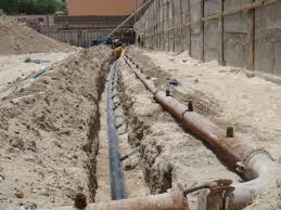 dewatering line.
A new system comprising of headers will be placed into these trenches and the existing well points will be connected to the same.
Once the new lines within the trenches are activated, upon checking for leaks, normal functioning, the trenches will be backfilled with aggregates over which further constructional activities will be carried out.
Dewatering pump will be placed at suitable locations in coordination with main contractor so that there won’t be any hindrance to the main contractor’s work.
Once the construction reaches sufficient level, dewatering can be stopped and opening in the raft can be closed.
Preventing The Migration of Fines
After observing the soil report it is evident that 10mm aggregate is the best suitable for filling the annular area to prevent any migration of the fines.
Discharge:
Discharge of ground water will be to the nearest available disposal point, subject to the N.O.C from relevant authorities, to be arranged by the Main Contractor.
Sedimentation tank will be kept to collect any fines present in the water.
Service of dewatering system:
Periodic service will be carried out according to the normal service schedule.